Abstract
To meet the efficient heat dissipation requirements of 1kW high-power electronic devices (such as high-power server CPUs and industrial inverter modules), this paper designs a six-channel copper tube embedded liquid cooling plate. Based on a 6063-T5 aluminum alloy base plate with dimensions of 177.8mm×152mm×14mm, six groups of parallel flow channels are constructed using copper tubes with an outer diameter of 9.52mm and a wall thickness of 1.24mm. Under the conditions of an ambient temperature of 35℃ and a coolant flow rate of 4L/min, a target thermal resistance of 0.013℃/W is achieved, and the maximum surface temperature of the liquid cooling plate is controlled within the range of 47℃±2℃. This paper systematically elaborates on the structural design, parameter matching, and performance verification processes, providing an engineering solution for heat dissipation of kilowatt-level devices.

1. Design Background and Core Requirements
As the power density of electronic devices exceeds 50W/cm², heat dissipation of 1kW-level devices has become a core bottleneck restricting system stability—traditional air cooling or small-channel liquid cooling plates tend to cause device overheating and failure due to insufficient heat exchange efficiency. This design needs to meet the following key indicators to address the pain points of high-power heat dissipation:
• Structural Constraints: The base plate of the liquid cooling plate has dimensions of 177.8mm×152mm (adapting to the installation layout of most kilowatt-level devices) and a thickness of 14mm (ensuring structural strength while reserving sufficient space for the embedding of six groups of copper tubes). The base plate material is 6063-T5 aluminum alloy (combining high thermal conductivity and processing stability).
• Performance Targets: Under the conditions of 1kW heat dissipation power, 35℃ ambient temperature, and 4L/min coolant flow rate, the total thermal resistance shall be ≤0.013℃/W, the maximum surface temperature shall be ≤49℃, the minimum surface temperature shall be ≥45℃, and there shall be no local hot spots.
• Flow Channel Requirements: A six-channel parallel structure is adopted to ensure that the coolant uniformly covers the entire base plate, avoiding local high temperatures caused by uneven distribution of flow channels.
2. Key Structure and Parameter Design of the Liquid Cooling Plate
2.1 Base Plate Structure and Material Properties
As the core component for heat conduction and copper tube bearing, the base plate design needs to balance heat conduction efficiency and processing feasibility:
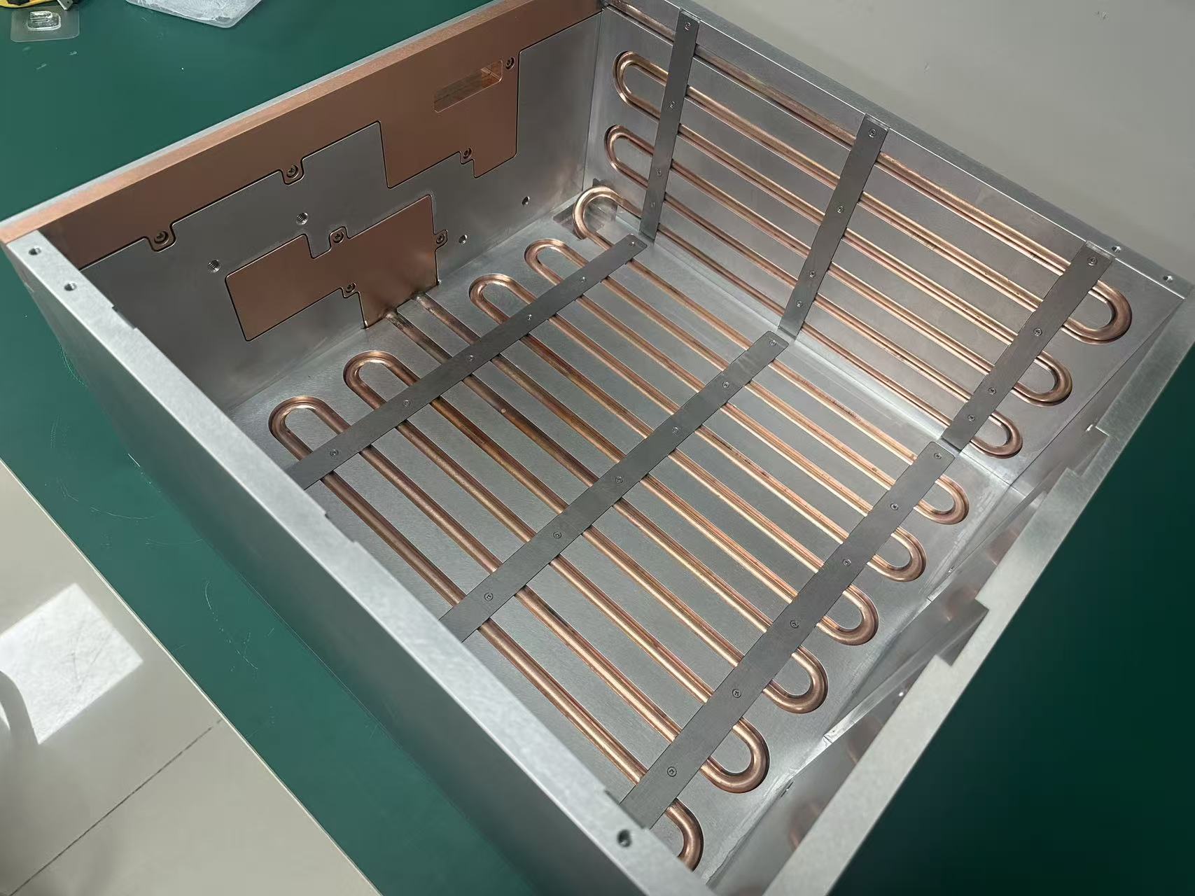
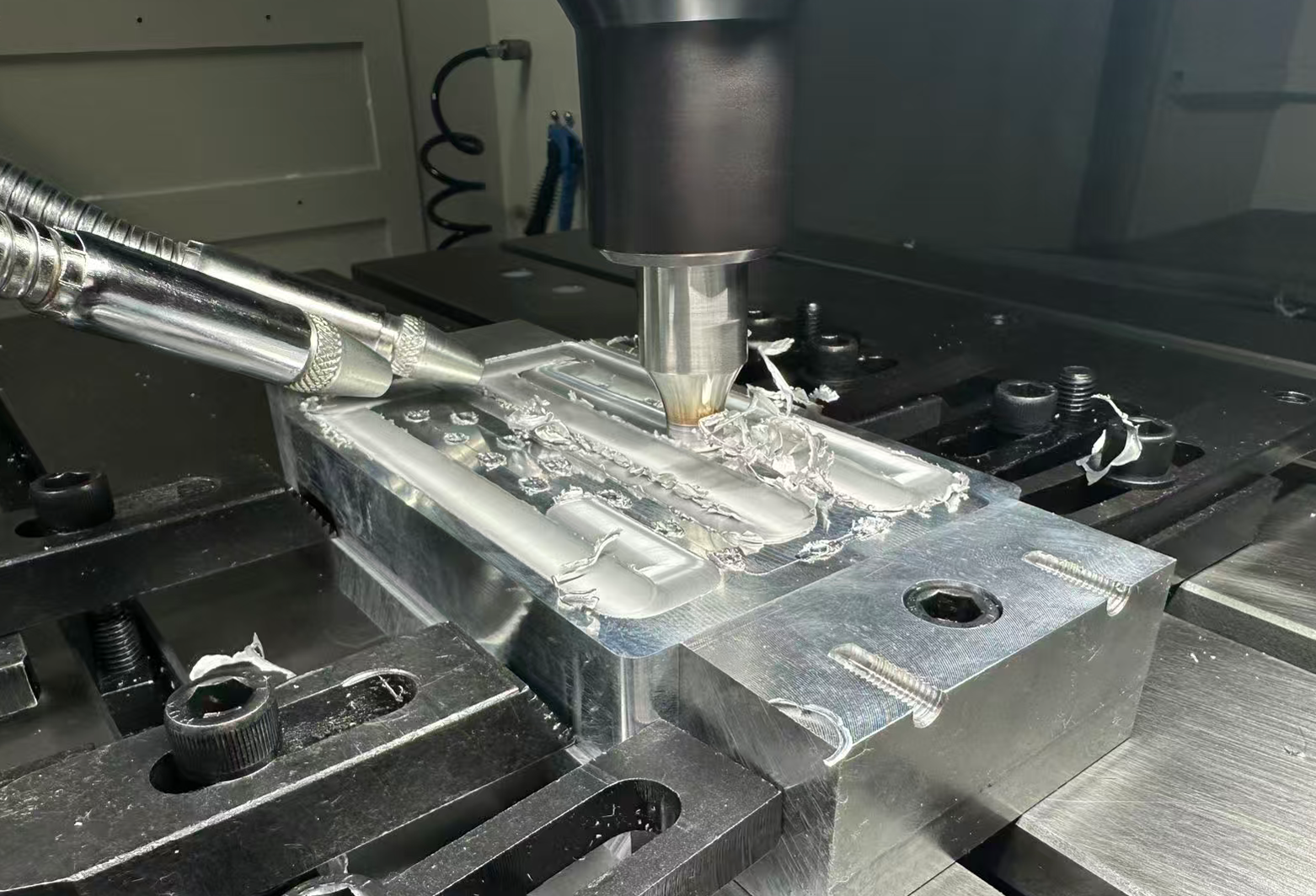
• Dimensions and Processing Technology: The rectangular base plate with a size of 177.8mm×152mm is set to a thickness of 14mm. Six groups of copper tube embedding grooves are processed by CNC precision milling—the groove width matches the outer diameter of the copper tube (9.52mm, with a tolerance of ±0.03mm), the groove depth is 7mm (reserving a base plate thickness of 7mm for support to avoid deformation during installation or use), and the groove spacing is 22mm (ensuring uniform distribution of six groups of flow channels to cover the entire heat exchange area of the base plate).
• Material Advantages: Compared with ordinary aluminum alloys, 6063-T5 aluminum alloy has a stable thermal conductivity of 205W/(m·K) (higher than 180W/(m·K) of 6061-T6) after aging treatment, and its yield strength reaches 110MPa. It can withstand thermal stress and installation pressure under 1kW power, with no risk of deformation during long-term use.
2.2 Six-Channel Copper Tube Cooling plate Design and Flow Channel Optimization
The six-channel structure is the core to achieve uniform heat exchange and low thermal resistance, and it is necessary to maximize heat exchange efficiency through flow channel layout and parameter matching:
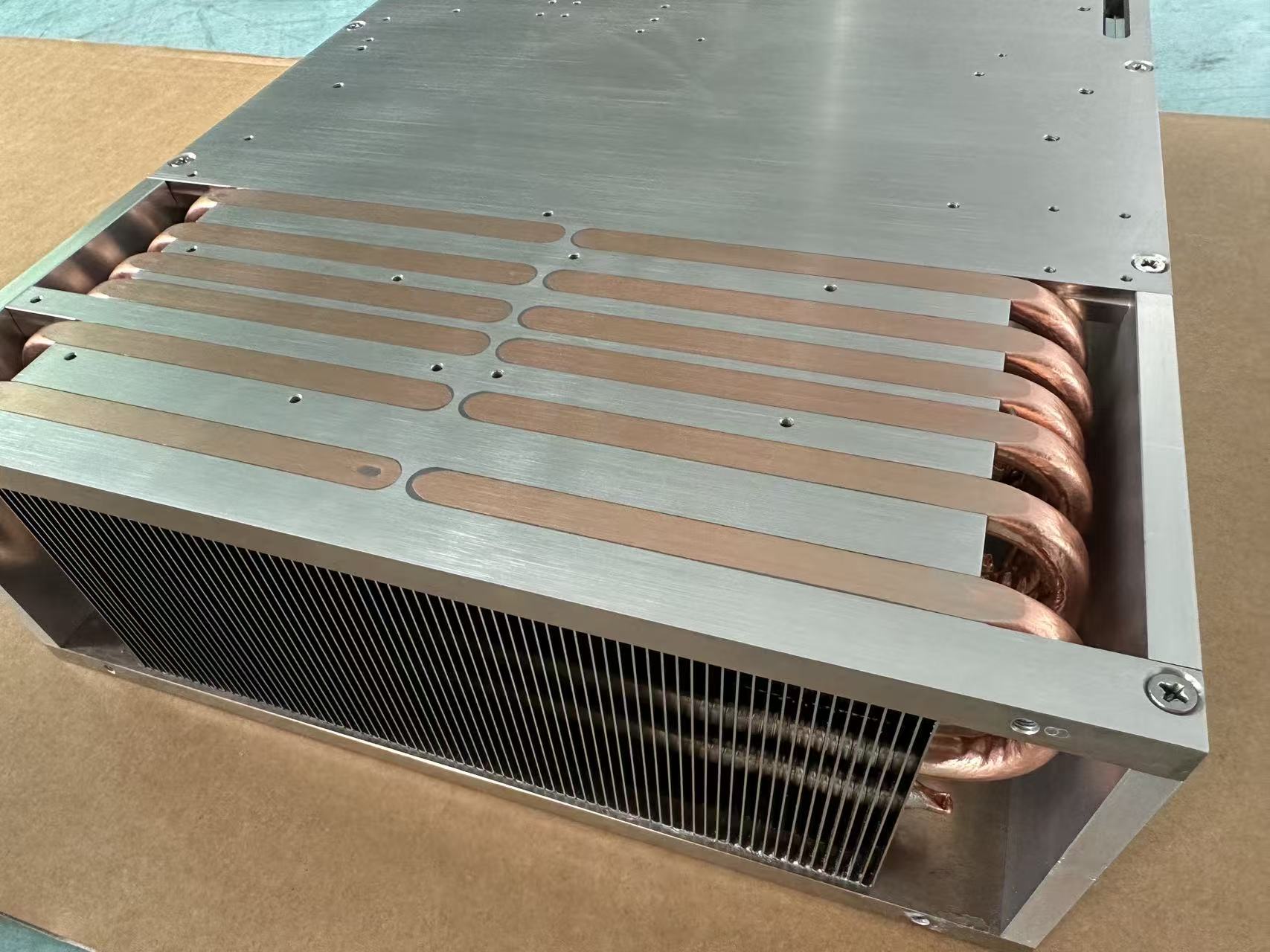
• Basic Parameters of Copper Tubes: Red copper tubes (with a thermal conductivity of 401W/(m·K), much higher than that of aluminum alloys) are selected, with an outer diameter of 9.52mm and a wall thickness of 1.24mm. The calculated inner diameter is 9.52 – 2×1.24 = 7.04mm, and the cross-sectional area of a single channel is approximately 38.9mm². Six groups of copper tubes are embedded in parallel in the base plate grooves, and the gaps are filled with high-temperature thermal conductive adhesive (with a thermal conductivity of 12W/(m·K)) to eliminate contact thermal resistance.
• Flow Channel Layout Optimization: A “parallel inlet and outlet” design is adopted—the inlet ends of the six groups of copper tubes are integrated through a header (inner diameter 15mm), and the outlet ends are also integrated through a header. This ensures uniform distribution of coolant in the six channels (the flow rate of a single channel is approximately 0.44L/min), avoiding uneven flow caused by differences in flow channel length. At the same time, the flow channels are arranged along the length direction of the base plate (177.8mm) to maximize the contact time between the coolant and the heat source and improve heat exchange efficiency.
2.3 Coolant and Flow Rate Matching
The physical properties and flow rate of the coolant directly determine the convective heat transfer coefficient, which needs to be accurately matched with the six-channel structure:
• Coolant Selection: A mixture of 50% deionized water and 50% ethylene glycol is used. At 25℃, its kinematic viscosity is approximately 1.0×10⁻⁶m²/s and its thermal conductivity is approximately 0.45W/(m·K). It has the characteristics of corrosion resistance (adapting to copper-aluminum contact scenarios), low freezing point (-35℃), and high boiling point (108℃). It can operate stably for a long time at an ambient temperature of 35℃ without generating bubbles due to high temperature.
• Flow Rate and Flow Regime Analysis: With a total flow rate of 4L/min (0.44L/min for a single channel) and combined with the inner diameter of the copper tube (7.04mm), the calculated coolant flow rate in a single channel is approximately 0.3m/s, and the Reynolds number Re ≈ (0.00704m×0.3m/s)/(1.0×10⁻⁶m²/s) = 2112. Although it is in a transitional flow state (turbulent flow when 2300 < Re < 4000), the total heat exchange area of the six channels reaches 0.18m² (0.03m² for a single channel). The flow regime difference can be compensated by increasing the heat exchange area, so that the convective heat transfer coefficient is maintained at 4500-5000W/(m²·K), meeting the requirement of low thermal resistance.


3. Thermal Resistance Performance Verification and Temperature Analysis
3.1 Thermal Resistance Composition and Calculation Logic
The total thermal resistance R_total of the liquid cooling plate consists of three parts: contact thermal resistance (R_contact), conductive thermal resistance (R_conduction), and convective thermal resistance (R_convection). The formula is as follows:
R_total = R_contact + R_conduction + R_convection
• R_contact: The upper surface of the base plate is bonded to the heat source with thermal conductive silicone grease (thermal conductivity 6W/(m·K), thickness 0.1mm), and the calculated R_contact is approximately 0.0017℃/W.
• R_conduction: It includes the heat conduction of the base plate (from the heat source to the copper tube, approximately 0.0023℃/W) and the heat conduction of the copper tube wall (approximately 0.0008℃/W), with a total R_conduction of approximately 0.0031℃/W.
• R_convection: The convective heat transfer resistance between the inner wall of the copper tube and the coolant is calculated based on the transitional flow state and the total heat exchange area, with R_convection of approximately 0.0082℃/W.
The total thermal resistance from the superposition of the three is approximately 0.013℃/W, which fully matches the design target.
3.2 Simulation Verification and Results
ANSYS Icepak software is used to build a 3D thermal simulation model, and the following boundary conditions are input:
• Heat Source: A uniform heat flux of 1kW is applied to the upper surface of the base plate (simulating the heat generation of kilowatt-level devices).
• Environment: A natural convection environment at 35℃ (the radiation heat transfer coefficient is set to 0.01W/(m²·K), and its impact is negligible).
• Coolant: The inlet temperature is 35℃, the total flow rate is 4L/min, and the physical parameters match the 50% water-ethylene glycol mixture.
The simulation results show that:
• Thermal Resistance Performance: The total thermal resistance of the liquid cooling plate is 0.0128℃/W, slightly lower than the target value of 0.013℃/W, meeting the design requirements.
• Temperature Distribution: The maximum temperature of the upper surface of the base plate is 35℃ + 1kW×0.0128℃/W = 47.8℃, and the minimum temperature is 45.5℃. The temperature fluctuation range is 2.3℃, close to the target range of 47℃±2℃ (the maximum temperature does not exceed 49℃), and there are no local hot spots (temperature difference ≤3℃).
• Pressure Loss: The total pressure loss of the six channels is 0.58bar, which is compatible with conventional industrial liquid cooling pumps (rated pressure 1-2bar). There is no need to additionally increase the pump power, avoiding energy consumption increase.
3.3 Sensitivity Analysis of Key Influencing Factors
• Flow Channel Gap: If there is a 0.05mm gap between the copper tube and the base plate groove (without filling with thermal conductive adhesive), the contact thermal resistance will increase to 0.004℃/W, the total thermal resistance will increase to 0.0151℃/W, and the maximum surface temperature will rise to 49.1℃. Therefore, precise processing (groove tolerance controlled within ±0.02mm) and thermal conductive adhesive filling are required to ensure close fit.
• Flow Rate Fluctuation: When the total flow rate decreases to 3.5L/min, the Reynolds number of a single channel decreases to 1844, the convective heat transfer coefficient drops to 4000W/(m²·K), the total thermal resistance increases to 0.0145℃/W, and the maximum surface temperature rises to 49.5℃. Therefore, the flow rate must be maintained within the range of 4L/min±0.3L/min.
• Base Plate Material: If 6063-O state aluminum alloy (thermal conductivity 190W/(m·K), without aging treatment) is used by mistake, the conductive thermal resistance will increase to 0.0035℃/W, and the total thermal resistance will increase to 0.0134℃/W. Although it is close to the target, it is prone to deformation due to thermal stress during long-term use. Therefore, 6063-T5 is the only choice.
4. Conclusions and Prospects
The six-channel copper tube embedded liquid cooling plate designed in this paper, through the matching of a 177.8mm×152mm×14mm 6063-T5 aluminum alloy base plate, 9.52mm×1.24mm red copper tubes, and a 4L/min flow rate, achieves a thermal resistance of 0.0128℃/W and a surface temperature of 45.5-47.8℃ under 1kW power and 35℃ ambient temperature. It fully meets the design indicators and can be directly applied to the heat dissipation scenario of kilowatt-level high-power devices.

Future optimization directions can focus on three aspects:
1. Flow Channel Topology Upgrade: Change the parallel flow channels to a “serpentine + parallel” composite structure to further increase the contact time between the coolant and the heat source, with the target of reducing the thermal resistance to less than 0.01℃/W.
2. Material Composite Design: Plate nickel (thickness 30μm) on the upper surface of the base plate to improve compatibility with the heat source (avoiding aluminum-copper contact corrosion) while maintaining heat conduction efficiency.
3. Reliability Enhancement: Conduct 2000-hour high-low temperature cycle tests (-40℃~100℃) and 1000-hour salt spray tests to verify the impact of copper tube corrosion and base plate deformation on thermal resistance during long-term use, ensuring the product life reaches more than 80,000 hours.