Design and Verification of a Liquid Cooling Plate Heat Dissipation Solution for 340Ah/104-Series Battery Modules
Driven by the “dual carbon” goals, the energy storage industry is ushering in a golden era of large-scale development. Lithium-ion batteries, as the core components of energy storage systems, have their thermal management capabilities directly determining the system’s safety, cycle life, and energy density. As energy storage batteries move toward higher capacity and greater integration, 340Ah-class battery modules have become the mainstream application choice. While the 104-series series-parallel design significantly boosts energy storage capacity, it also presents more severe heat dissipation challenges—if the Joule heat generated during battery charging and discharging cannot be dissipated in a timely manner, it will lead to an increase in the internal temperature gradient of the module and trigger the risk of thermal runaway. Against this backdrop, this paper proposes a liquid cooling plate heat dissipation solution based on 6063 aluminum alloy profiles, which achieves efficient thermal management of 340Ah/104-series battery modules through precise flow channel design and performance testing.
I. Core Design Parameters and Material Selection of the Liquid Cooling Plate
(1) Rationale for Material Selection
The material of the liquid cooling plate directly affects heat dissipation efficiency and structural stability. This solution adopts 6063 aluminum alloy profiles as the base material of the liquid cooling plate, which boasts three core advantages: first, it has an excellent thermal conductivity coefficient of up to 201 W/(m·K), enabling rapid heat transfer between the battery and the cooling liquid; second, it features good formability, allowing the fabrication of complex internal flow channels via extrusion processes to meet customized heat dissipation needs; third, it has strong corrosion resistance, and when paired with compatible cooling liquids, it can maintain structural integrity during the long-term operation of energy storage systems, while also achieving a balance between lightweight design and cost-effectiveness, aligning with the industry trend of cost reduction and efficiency improvement for energy storage equipment.
(2) Key Structural and Performance Parameters
Tailored to the dimensions and heat dissipation requirements of 340Ah/104-series battery modules, the core parameters of the liquid cooling plate designed in this solution are as follows:
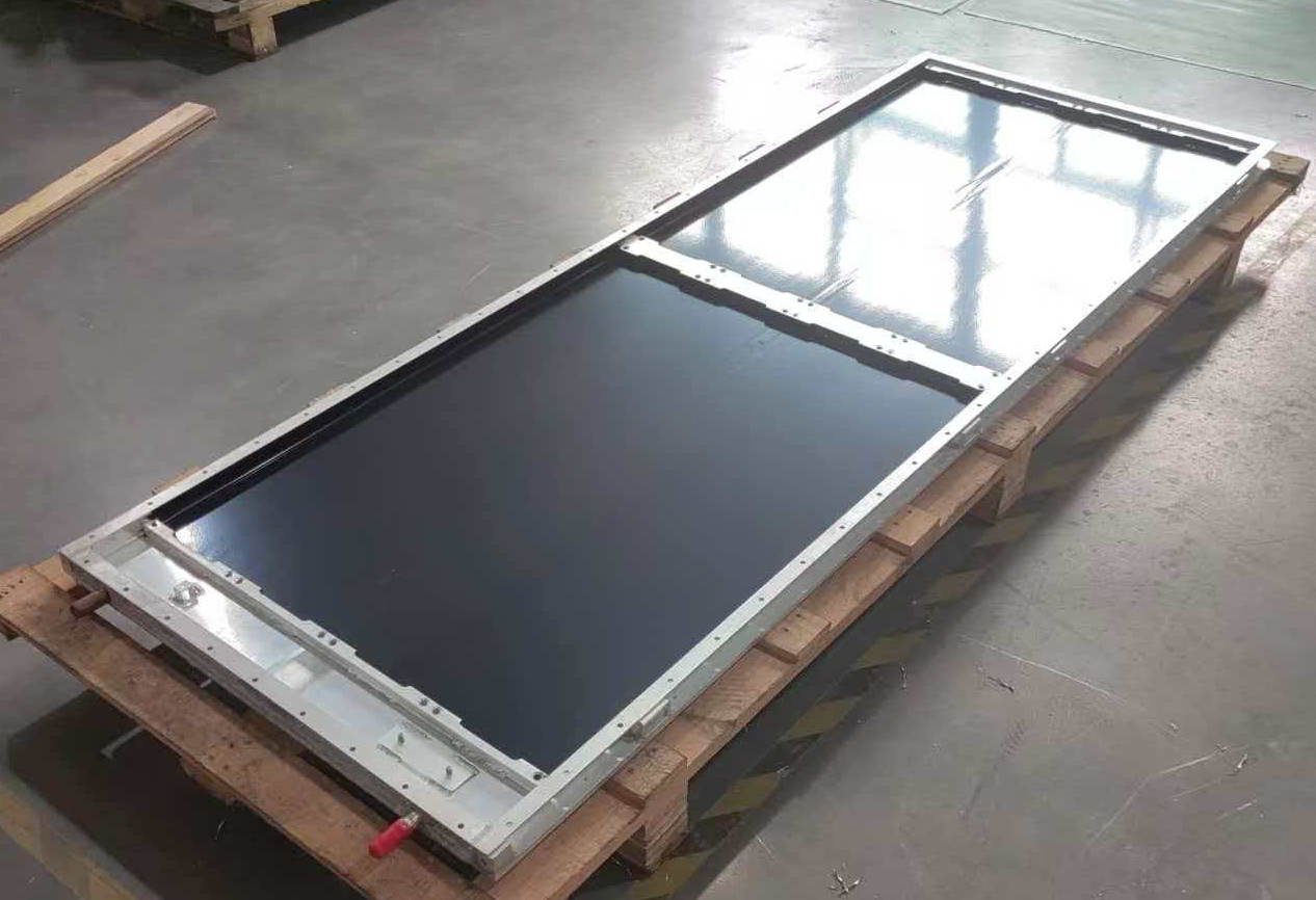
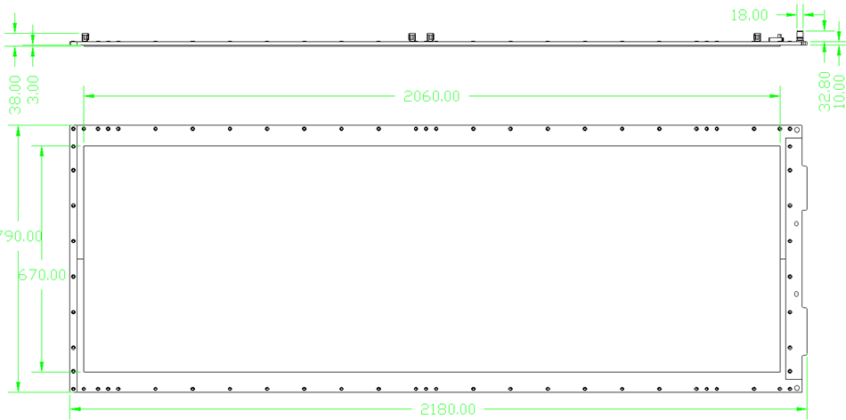
1. Overall Dimensions: 2180mm × 790mm × 10mm, which perfectly matches the contact surface of the battery module, ensuring full contact between the liquid cooling plate and battery cells to minimize contact thermal resistance;
2. Coolant Flow Rate: Set at 15L/min, which has been verified through simulation and experiments to ensure sufficient heat exchange between the coolant and the inner wall of the liquid cooling plate, while avoiding increased pump power consumption and flow channel noise caused by excessively high flow rates;
3. Inlet and Outlet Design: Adopts interface specifications with an outer diameter of 18mm, which is compatible with the cooling pipelines of energy storage systems, facilitating on-site installation and pipeline connection, while also meeting the requirements for large-flow coolant delivery;
4. Flow Channel Structure: Integral extrusion-molded flow channels are adopted, and the layout of the flow channels follows the principle of “uniform distribution and proximal heat dissipation”. The flow channel direction and cross-sectional dimensions are optimized through simulation, ensuring uniform temperature distribution on the surface of the liquid cooling plate with a maximum temperature difference controlled within ±2℃.
II. Heat Dissipation Principle and Adaptability Analysis of the Liquid Cooling Plate
During the charging and discharging process of the 340Ah/104-series battery module, each battery cell generates heat, which is transferred to the surface of the liquid cooling plate through the battery casing. The coolant inside the liquid cooling plate flows continuously at a rate of 15L/min driven by the pump, and undergoes forced convection heat exchange with the inner wall of the liquid cooling plate as it flows through the channels, carrying away the heat and transferring it to the cooling unit of the energy storage system, thus realizing the cyclic dissipation of heat.
In terms of adaptability, the advantages of this solution are reflected in two dimensions: first, structural adaptability, the 10mm thickness of the 6063 aluminum alloy profile liquid cooling plate balances structural strength and heat dissipation efficiency, and the 2180mm × 790mm dimensions can fully cover the arrangement area of the 104-series battery module, ensuring uniform heat dissipation for each series of batteries; second, performance adaptability, the 15L/min flow rate design can precisely match the heat generation power of the 340Ah battery. Calculations show that under this flow rate, the heat dissipation power of the liquid cooling plate can meet the heat dissipation requirements of the module under 1C charging and discharging rates, effectively controlling the battery operating temperature within the optimal range of 25℃-35℃.
III. Reliability Testing and Performance Verification
To ensure the stability of the liquid cooling plate during the long-term operation of energy storage systems, this solution has conducted multi-dimensional reliability testing and performance verification experiments.
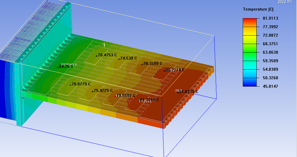
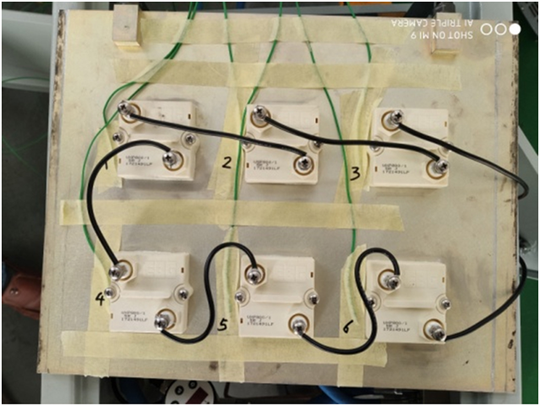
(1) Heat Dissipation Performance Testing
In a constant-temperature laboratory environment, the liquid cooling plate was assembled with the 340Ah/104-series battery module to simulate 1C charging and discharging cycle conditions. Test results show that during continuous charging and discharging, the maximum temperature of the battery module was 34.87℃, the minimum temperature was 32.58℃, and the maximum temperature difference was only 1.7℃, far lower than the industry standard limit of 5℃. Meanwhile, the temperature difference between the inlet and outlet of the coolant was stably maintained at 2℃, indicating that the heat exchange efficiency of the liquid cooling plate was within a stable range, capable of effectively dissipating the heat generated by the battery.

(2) Reliability Testing
1. Pressure Resistance Test: The liquid cooling plate was subjected to a pressure resistance test at 1.5 times the working pressure for a continuous holding time of 30 minutes, with no leakage or deformation observed, verifying the sealing performance and structural strength of the flow channel structure;
2. Thermal Cycle Test: Simulating the actual operating environment of the energy storage system, thermal cycle tests were conducted between -40℃ and 85℃. After 1000 cumulative cycles, the thermal conductivity of the liquid cooling plate showed no significant attenuation, and no cracks or corrosion were detected on the surface of the profiles;
3. Long-term Operation Test: The liquid cooling plate was installed in an energy storage system for continuous operation testing. After more than 5000 hours of cumulative operation, the heat dissipation efficiency of the liquid cooling plate remained stable, with no failures such as flow channel blockage or interface leakage.
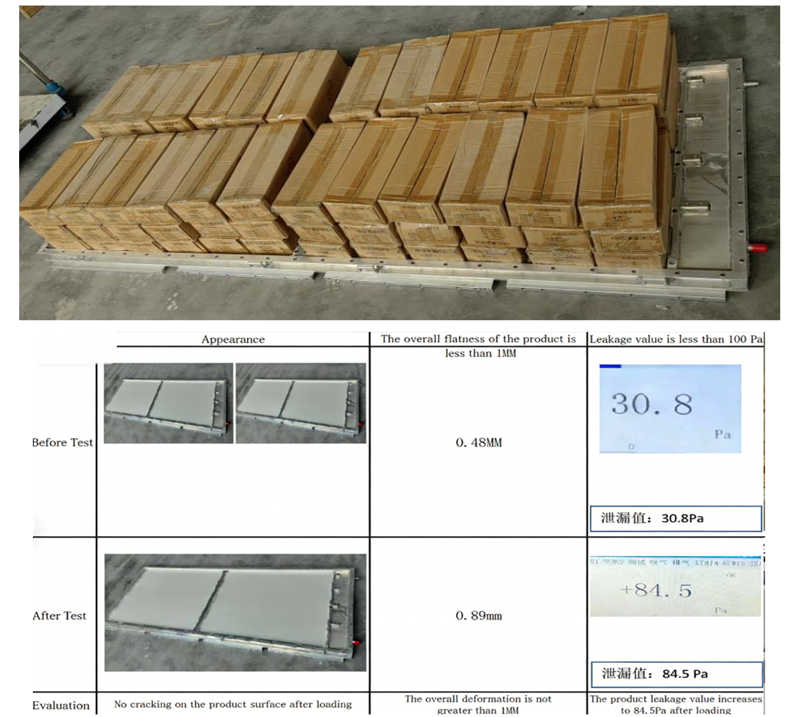
4,Load bearing test
The product simulation module is subjected to a load of 350KG and placed statically for 3 days. Subsequently, conduct comparisons of flatness data and airtight leakage rate, and inspect the surface for cracks.
Leakage test conditions:
Pressure 350 kPa,
Inflation time 40 s,
Pressure holding time 120 s,
Detection time 60 s,
Leakage rate < 100 Pa
IV. Industry Application Value and Development Outlook
This liquid cooling plate heat dissipation solution based on 6063 aluminum alloy profiles, with its customized design for 340Ah/104-series battery modules, not only solves the heat dissipation challenges of high-capacity energy storage batteries but also aligns with the industry trend of “high safety, high integration, and low cost” in the energy storage sector. At the application level, the liquid cooling plate can flexibly adjust the flow channel layout, overall dimensions, and interface specifications according to the battery module dimensions and heat dissipation requirements of different customers, realizing personalized “custom-made” services.
With the expansion of energy storage industry applications to grid-scale and industrial-commercial scale, the capacity and integration level of battery modules will continue to increase, making the importance of thermal management systems more prominent. In the future, we will further optimize the flow channel simulation algorithm of the liquid cooling plate, explore the matching schemes of new thermal conductive coatings and high-efficiency coolants, continuously improve heat dissipation efficiency and reliability, and provide solid thermal management technical support for the high-quality development of the energy storage industry.
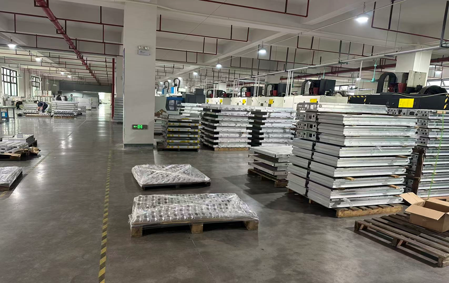
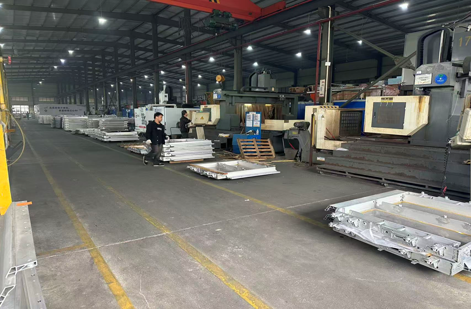
Kenfa factory capacity of producting these cold plate :
A 50,000-square-meter workshop with a monthly production capacity of 10,000 units.
CORE TECHNICAL PARAMETERS
1,Material: Al 6063-T6, yield strength ≥170 Mpa, tensile strength ≥215 Mpa;
2, Spray Coating Requirements:
For the cold plate top surface (water nozzles and visible threaded fastener areas): spray epoxy resin (no silicone-based materials such as silicone oil or RAL9005 colorant), coating thickness ≥250 μm; insulation withstand voltage: 2500 VDC for 60 s,insulation resistance ≥500 MΩ; 4380 VDC for 60 s, leakage current ≤1 mA. For other surfaces: overall plastic spraying with RAL9005 black.(matte finish), coating thickness 40-100 μm. Adhesion strength: tested per GB/T9286, reaching Grade 0-1.
3,Dimensional Tolerance: Follow 3D drawing; flow rate 14 L/min,
deviation of flow uniformity for each stream <15%.
4,Performance Requirement: Temperature difference on the upper surface
of the core ≤40 °C (maximum temperature <40 °C), pressure drop <2 kPa.
5, Form and Position Tolerance: Comply with GB/T 1184-1996 (Grade K);
profile reference GB/T 25239-2010.
6, IP Protection & Air Tightness (Cabinet)After assembly, the cabinet shall meet IPX7 protection grade. Inflate to 10 kPa, hold pressure for 60 s, test for 60 s, leakage rate ≤100 Pa·m³/min.
7,Cold Plate Flow Channel Tightness 100% air tightness inspection is
required for the cold plate flow channel. Sampling inspection criteria:
pressure 0.3 MPa, hold for 60 s, test for 60 s, leakage rate <2×10⁻⁶ Pa·m³/s;
or differential pressure leak test: air pressure 0.3 MPa, hold for 60 s, test for 60 s, leakage rate ≤60 Pa.
8,Fastener Torque Destruction torque of threaded fasteners (M5, M6, M10)
≥9.7 N·m, 17 N·m, 66 N·m respectively.
9, Locknut Specifications
Hex socket head type locknuts are adopted, material is carbon steel with
zinc-nickel plating, strength grade 8.8. The nuts shall pass a salt spray
test: no white rust after 144 h, no red rust after 720 h.
10, Welding Precision & Process, To ensure component precision, welding jigs shall be used if necessary to guarantee assembly accuracy. Friction stirwelding is adopted for bottom plate splicing and front/rear head welding;the overall weld shall be firm and free of defects, and partial welding areas shall be ground flat after welding.
11, Welding Strength. Friction stir welding strength ≥75% of the base metal strength (GB/T 34630.4);Arc welding strength ≥65% of the base metalstrength (GB/T 19869.2).
12, Cold Plate Internal Cleanliness. Total mass of foreign matter ≤30 mg;hard particles (e.g., sand) with diameter ≤1 mm, no metal particles;
soft particles with diameter ≤2×1 mm; Ultrasonic cleaning for ≥18 min (200-mesh filter), rinse for 3 min.
13, Appearance Requirements: The surface shall be smooth without burrs, flash, weld spatter, porosity, lack of fusion, obvious scratches, etc., with surface roughness Ra3.2;No residual aluminum is allowed in threaded holes; spattered metal or other contaminants on welds and adjacent parts shall be removed by mechanical methods and wiped clean with organic solvent.
15Packaging Requirements. The product shall be packaged firmly with moisture-proof and anti-corrosion measures.
16. Service Life. The product service life shall be more than 5-8 years.
For any technical consultation or sample customization, please feel free to email us. We will handle your request promptly, and we will go all out to assist you even if you only need a single sample.
our email : king@kenfatech.com