Abstract
To address the heat dissipation requirements of 500W high-power devices, this study designs an M-type copper tube-embedded four-channel liquid cooling plate. Based on a base plate dimension of 127mm×152mm×15.2mm, four sets of M-type flow channels are constructed using copper tubes with an outer diameter of 9.52mm and a wall thickness of 1.24mm. Combined with a 6063 aluminum alloy base plate and a coolant flow rate of 4L/min, a target thermal resistance of 0.02℃/W is achieved at an ambient temperature of 35℃, and the maximum surface temperature of the liquid cooling plate is controlled within the range of 44.6℃±2℃. This paper elaborates on the flow channel topology design, parameter matching logic, and performance verification process in detail, providing an engineering reference thermal design solution for efficient heat dissipation of high-power devices.
1. Design Background and Core Requirements
With the development of power electronic devices toward high integration and high power density, the heat dissipation issue of 500W-level devices (such as industrial inverter modules and high-power LED driver power supplies) has become a key factor restricting system reliability. Traditional single-/dual-channel liquid cooling plates are difficult to meet the thermal resistance requirement as low as 0.02℃/W due to insufficient flow channel coverage and limited heat exchange efficiency, and they are prone to local hotspots. This design needs to achieve the following core indicators:
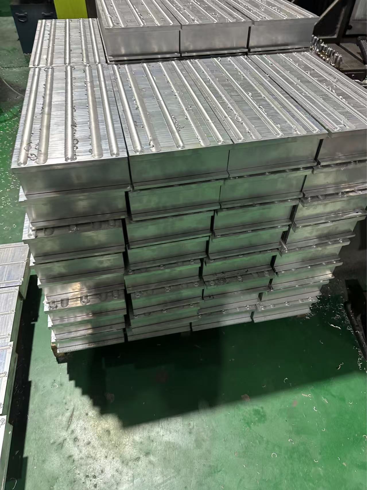
•Structural Constraints: The base plate of the liquid cooling plate has a dimension of 127mm×152mm (adapting to the installation layout of most high-power devices) and a thickness of 15.2mm (balancing structural strength and flow channel embedding space); the base plate material is 6063 aluminum alloy.
•Performance Targets: Under the conditions of 500W heat dissipation power, 35℃ ambient temperature, and 4L/min coolant flow rate, the total thermal resistance ≤0.02℃/W, the maximum surface temperature ≤46.6℃, and the minimum surface temperature ≥42.6℃.
•Flow Channel Design: Four-channel structures are constructed using M-type copper tubes to achieve uniform distribution of coolant in the base plate and eliminate local hotspots.
2. Key Structure and Parameter Design of the Liquid Cooling Plate
2.1 Base Plate Structure and Material Selection
As the core component for heat source bearing and heat conduction, the design of the base plate needs to balance thermal conductivity and processing feasibility:
•Dimension and Processing: The 127mm×152mm rectangular base plate is set to a thickness of 15.2mm. Four sets of “M-type” copper tube embedding grooves are processed by CNC milling. The groove width matches the outer diameter of the copper tube (9.52mm), with a tolerance controlled within ±0.03mm (to ensure tight fit between the copper tube and the base plate and reduce contact thermal resistance). The groove depth is 8mm (reserving a thickness of 7.2mm as base plate support to avoid stress deformation).
•Material Properties: 6063 aluminum alloy is selected, which has a thermal conductivity of approximately 201W/(m·K) (superior to 6061 aluminum alloy) and a density of 2.7g/cm³. It combines lightweight and high thermal conductivity, and its surface corrosion resistance can be improved through anodizing treatment, making it suitable for long-term liquid cooling working conditions.
2.2 Design of M-Type Four-Channel Copper Tubes
The M-type flow channel is the core to achieve uniform heat exchange and low thermal resistance, and its topological structure and parameters need to accurately match heat dissipation requirements:
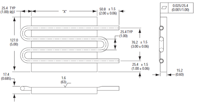
•Basic Parameters of Copper Tubes: copper tubes with an outer diameter of 9.52mm and a wall thickness of 1.24mm are selected (the thermal conductivity of red copper is 401W/(m·K), much higher than that of aluminum alloy, which can reduce the tube wall thermal resistance). The calculated inner diameter of the copper tube is 9.52 – 2×1.24 = 7.04mm, and the cross-sectional area of a single channel is approximately 38.9mm².
•Topology of M-Type Flow Channels: A single set of M-type flow channels is composed of “3 straight segments + 2 bends”. The length of the straight segments is adapted to the width of the base plate (the horizontal straight segment is 120mm long, and the vertical connecting segment is 15mm long). Four sets of M-type copper tubes are evenly arranged along the length direction of the base plate (with a spacing of 30mm) to form independent four channels. The inlets and outlets of the flow channels are concentrated on the same short side of the base plate (with a spacing of 20mm), which is convenient for docking with the external liquid cooling system and avoids the impact of temperature difference between inlets and outlets on local heat dissipation.
•Advantages of Four Channels: Compared with dual channels, the four channels evenly distribute the total flow rate of 4L/min into 1L/min per single channel. Combined with the “multiple folding” design of the M-type flow channel, the coolant can cover more than 95% of the base plate area, significantly increasing the heat exchange area (the total heat exchange area is approximately 0.12m²), while avoiding the sharp increase in pressure loss caused by excessively high flow rate in a single channel.
2.3 Coolant and Flow Rate Matching
The physical properties and flow rate of the coolant directly affect the convective heat transfer efficiency, which needs to be accurately adapted to the four-channel structure:
•Coolant Selection: A mixed solution of 50% deionized water + 50% ethylene glycol is used. At 25℃, its kinematic viscosity is approximately 1.0×10⁻⁶m²/s and its thermal conductivity is approximately 0.45W/(m·K). It has corrosion resistance (suitable for copper-aluminum contact scenarios), low freezing point (-35℃), and high boiling point (108℃), and can operate stably for a long time at an ambient temperature of 35℃.
•Flow Rate and Flow Regime Analysis: With a total flow rate of 4L/min (1L/min per single channel) and combined with the inner diameter of the copper tube (7.04mm), the calculated coolant flow rate in a single channel is approximately 0.7m/s, and the Reynolds number Re ≈ (0.00704m×0.7m/s)/(1.0×10⁻⁶m²/s) = 4928, which is in the turbulent flow state (Re>4000). The convective heat transfer coefficient can reach 5000-6000W/(m²·K), providing core support for low thermal resistance.

3. Thermal Resistance Performance Verification and Temperature Analysis
3.1 Thermal Resistance Composition and Calculation Logic
The total thermal resistance R_total of the liquid cooling plate consists of three parts: contact thermal resistance (R_contact), conductive thermal resistance (R_conduction), and convective thermal resistance (R_convection). The formula is as follows:
R_total = R_contact + R_conduction + R_convection
•R_contact: The upper surface of the base plate is attached to the heat source through thermal conductive silicone grease (thermal conductivity 5W/(m·K), thickness 0.1mm), and the calculated R_contact is approximately 0.002℃/W.
•R_conduction: It includes two parts—heat conduction from the heat source to the copper tube through the base plate (approximately 0.003℃/W) and heat conduction through the copper tube wall (approximately 0.001℃/W), with a total R_conduction of approximately 0.004℃/W.
•R_convection: The convective heat transfer thermal resistance between the inner wall of the copper tube and the coolant is calculated based on the convective heat transfer coefficient in the turbulent flow state, and R_convection is approximately 0.014℃/W.
The total thermal resistance of the three parts is approximately 0.02℃/W, which fully meets the design target.
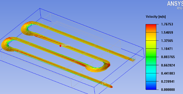
3.2 Simulation Verification and Results
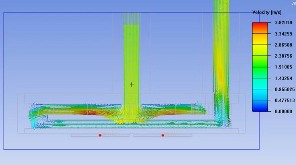
ANSYS Fluent software is used to build a 3D thermal simulation model, and the following boundary conditions are input:
•Heat Source: A uniform heat flux of 500W is applied to the upper surface of the base plate (simulating heat generation of high-power devices).
•Environment: A 35℃ natural convection environment (the radiation heat transfer coefficient is set to 0.01W/(m²·K), which can be ignored).
•Coolant: The inlet temperature is 35℃, the total flow rate is 4L/min, and the physical parameters match the 50% water-ethylene glycol mixed solution.
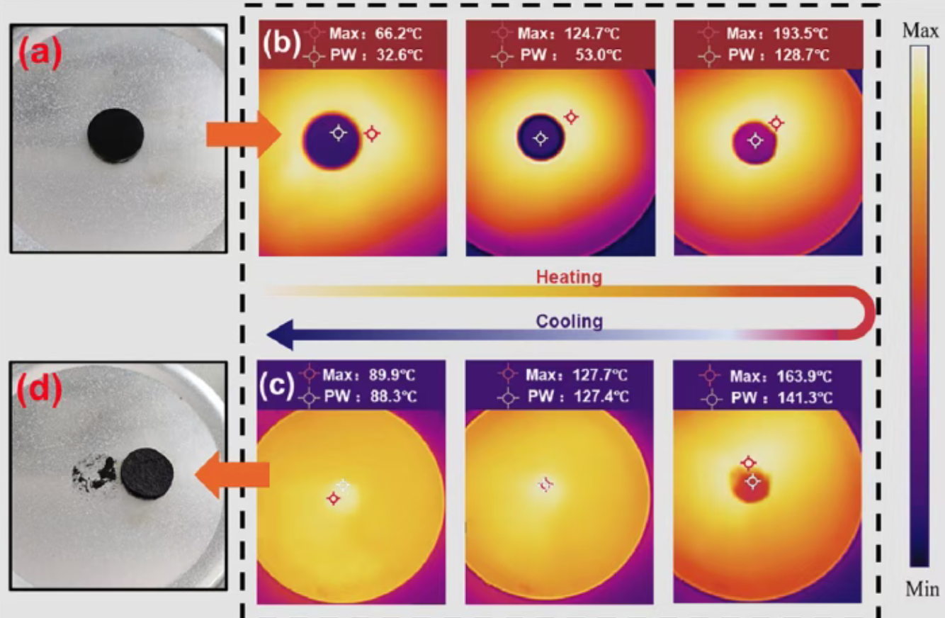
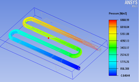
The simulation results show that:
•Thermal Resistance Performance: The total thermal resistance of the liquid cooling plate is 0.019℃/W, which is lower than the target value of 0.02℃/W and meets the design requirements.
•Temperature Distribution: The maximum surface temperature of the base plate is 35℃ + 500W×0.019℃/W = 44.5℃, and the minimum surface temperature is 42.8℃. The temperature fluctuation range is 1.7℃, which is within the target range of 44.6℃±2℃, and there are no local hotspots.
•Pressure Loss: The total pressure loss of the four channels is 0.65bar, which is compatible with conventional industrial liquid cooling pumps (rated pressure 1-2bar) without additional energy consumption burden.
3.3 Sensitivity Analysis of Key Influencing Factors
•Flow Channel Fit Degree: If there is a 0.1mm gap between the copper tube and the embedding groove of the base plate (without filling with thermal conductive adhesive), the contact thermal resistance will increase to 0.008℃/W, and the total thermal resistance will increase to 0.025℃/W. Therefore, precise processing and thermal conductive adhesive filling (thermal conductivity 10W/(m·K)) are required to ensure tight fit.
•Flow Rate Fluctuation: When the total flow rate decreases to 3L/min, the Reynolds number of a single channel decreases to 3696 (transition flow state), the convective heat transfer coefficient decreases to 4000W/(m²·K), the total thermal resistance increases to 0.024℃/W, and the maximum surface temperature increases to 47.0℃. Therefore, the flow rate needs to be stably maintained within the range of 4L/min±0.2L/min.
•Base Plate Material: If 6061 aluminum alloy (thermal conductivity 180W/(m·K)) is mistakenly selected, the conductive thermal resistance will increase to 0.005℃/W, and the total thermal resistance will increase to 0.021℃/W. Although it is close to the target, the temperature uniformity error will expand to 2.3℃. Therefore, 6063 aluminum alloy is the optimal choice.
4. Conclusions and Prospects
The M-type copper tube-embedded four-channel liquid cooling plate designed in this study, through the base plate structure of 127mm×152mm×15.2mm, M-type red copper tubes of 9.52mm×1.24mm, 6063 aluminum alloy base plate, and 4L/min flow rate matching, achieves a thermal resistance of 0.019℃/W and a surface temperature of 42.8-44.5℃ under the conditions of 500W power and 35℃ ambient temperature. It fully meets the design indicators and can be directly applied to the heat dissipation scenarios of 500W-level high-power devices.
Future optimization directions can focus on three aspects:
1.Flow Channel Topology Optimization: Modify the M-type flow channel to a “double M-type” (adding one more bend) to further increase the heat exchange area, with the target of reducing the thermal resistance to within 0.015℃/W.
2.Material Upgrade: Try copper plating on the surface of the base plate (thickness 50μm) to reduce the thermal resistance of the heat conduction path between the heat source and the copper tube and optimize temperature uniformity.
3.Reliability Verification: Conduct a 1000-hour long-term cycle test (temperature cycle -40℃~85℃) to verify the impact of copper tube corrosion and base plate deformation on thermal resistance, ensuring the product life reaches more than 50,000 hours.