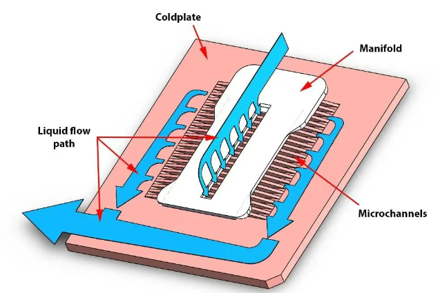
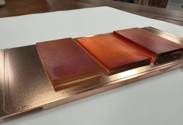
Abstract:The direct cooling technology (battery cold plate) of the power battery pack has advantages such as high cooling efficiency, compact system design, and no hidden risks of short circuits, and it is receiving increasing attention. However, the complexity of the direct cooling technology poses new challenges for simulation, including intense phase change processes within the battery pack, large temperature differentials within the battery cells, and high integration with HVAC control strategies. This article will introduce the simulation method of GT-SUITE in direct cooling of battery packs. This method can balance the resolution and computational speed of the battery, and it is suitable for long-term transient simulations.
The optimal temperature range for lithium batteries used in electric vehicles is between 20 and 30 degrees Celsius. High temperatures (above 45 degrees Celsius) accelerate battery aging and increase the risk of thermal safety issues. On the other hand, low temperatures (below 0 degrees Celsius) limit the charging and discharging performance of the battery pack and increase the risk of lithium plating. Therefore, thermal management of the battery pack is crucial.
Currently, the combination of a heat pump air conditioning system and a liquid cooling system for the battery pack has become the mainstream solution for thermal management in electric vehicles. Liquid cooling technology offers the advantage of fast cooling, but the secondary circulation of the liquid cooling system leads to more components, higher costs, and a risk of leakage. For this reason, direct cooling technology is gaining more attention. Direct cooling eliminates the need for a secondary cooling liquid circulation by using refrigerant boiling heat transfer instead of single-phase heat exchange with a cooling liquid. It offers high cooling efficiency and requires fewer components, effectively reducing the overall vehicle weight and improving specific energy and cost-effectiveness. However, direct cooling technology comes with a more complex control system.
In terms of simulation, direct cooling technology also presents new challenges. These challenges mainly revolve around three aspects: intense phase change processes within the battery pack, significant temperature differences within the battery cells (requiring high-resolution models), and the need for high integration with HVAC control strategies. This article will introduce the simulation method of GT-SUITE in direct cooling of battery packs. This method can balance the resolution and computational speed of the battery, making it suitable for long-term transient simulations.
There are three main methods for the simulation of direct-cooled battery packs.
3D CFD method
CFD simulation models provide high fidelity and can effectively simulate the parameter distribution within the battery pack. However, due to the intense phase change processes occurring inside the battery pack, convergence becomes challenging. Additionally, the high computational cost of CFD simulations often leads to a simplified approach where the refrigerant circuit is not explicitly modeled, and only the boundaries of the battery pack are defined. Unfortunately, in many cases, obtaining accurate boundary conditions for the battery pack is difficult. Furthermore, direct cooling technology is closely integrated with the HVAC system and control strategies (such as compressors and electronic expansion valves), which cannot be adequately captured by CFD simulations. Although one-dimensional or three-dimensional coupling approaches can address the convergence issues of standalone CFD simulations, they are computationally expensive and not practical for most applications

System simulation method – the cell is divided into several hot nodes
In response to the difficulties encountered by CFD simulations in simulating direct cooling technology, especially the challenges related to high integration with HVAC control strategies, system simulation has been embraced by many researchers and engineers. Due to the significant temperature variations within battery cells in direct cooling, treating each cell as a single thermal node is inadequate. Therefore, in system simulations, battery cells are often divided into multiple thermal nodes to account for approximate internal temperature differences. This approach provides fast computation, enables integration with HVAC control strategies, but maintains a relatively low model resolution.

System simulation method — The cell is divided into finite element
To improve the resolution of the model while integrating the HVAC and control strategies, the GT-SUITE can divide the cell into finite elements, as shown below, with each cell divided into 960 grids (the number of grids is related to the grid size).

Cell temperature at different charging ratios
A battery pack model with a given boundary (not integrated with the HVAC system) was used. The ambient temperature was 43 ° C, the refrigerant flow rate was given 0.05kg/s, the inlet dryness was 0.3, and the outlet pressure was 3bar. The battery was charged at 1/2/3C, and the SOC charging window was 0.3 to 0.8. The following figures show the temperature profiles of the monomer located in the middle of the module at different charging ratios, respectively.


The battery pack model is integrated with the HVAC system. The opening of the electronic expansion valve at the front of the battery pack was adjusted by PI, and the influence of different target superheat (1/2/3℃) at the outlet of the battery pack on the results was investigated.
The ambient temperature is 43℃, the inlet wind speed of the condenser is 5m/s and the inlet air temperature is 43℃, and the battery is discharged at 1C. The control strategy in this example is very simple (for example only), that is, the compressor controls the target air temperature of the evaporator by PI to 3 ° C, when the high pressure pressure is greater than 25bar, reduce the compressor speed to 1000rpm, and then output the output value of the PI controller after 30s. The following figure shows the speed of the compressor at different target superheat at the outlet of the battery pack. It can be seen from the figure that the compressor switches frequently. The greater the target superheat, the smaller the flow through the battery pack, resulting in higher pressure in the air conditioning system, which in turn continuously triggers the pressure switch.
In summary, therefore, for the heat dissipation of the battery pack, it is usually necessary to do simulation analysis, to know the temperature distribution inside the battery pack, so as to improve the design. Of course, any analysis is not the only one, it is just a guide for our design.For any thermal management needs, please contact us.Kenfa tech is an expert in heat sinks,liquid cold plate design and production.


