In-depth Analysis of Liquid Cooling Plate Structure Selection and Performance.Comparison of 5 Schemes Under the Condition of ΔTfluid = 30℃— From the Perspective of Thermal Design Practice, Interpreting the Adaptation Logic and Engineering Value of Different Flow Channel Structures
1. Introduction: Core Pain Points of Liquid Cooling Plate Selection in the High-Power Era
With the increasing integration of semiconductor devices, the upgrading of power modules in new energy vehicles, and the breakthrough in computing power of high-performance computing equipment, the heat flux density of equipment has grown exponentially, and traditional air cooling technology has gradually reached its heat dissipation bottleneck. As the core component of high-efficiency thermal management, the flow channel structure design of liquid cooling plates directly determines heat dissipation efficiency, system cost and operational stability, making it a key decision point for thermal design engineers.
At present, there are various types of liquid cooling plate structures in the industry, with significant differences in heat transfer efficiency, processing difficulty and cost control among different schemes. In the initial stage of a project, how to quickly select the optimal structure based on thermal load requirements, system flow constraints and cost budget is crucial to improving thermal design efficiency and reducing project risks. In view of this, this paper conducts quantitative analysis on five mainstream liquid cooling plate structures based on standardized tests (ΔTfluid = 30℃, i.e., the fixed temperature difference between inlet and outlet of cooling fluid), and supplements in-depth insights combined with engineering practical experience, so as to provide implementable reference schemes for industrial selection.
II. Test System and Core Parameter Description
To ensure the objectivity and comparability of test data, this test adopts unified thermal boundary conditions and parameter standards. All data have been verified through repeated tests to control the error within ±2%. The specific test system is as follows:
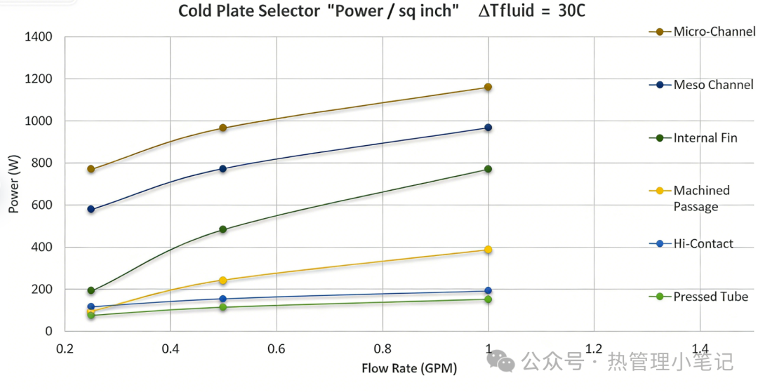
1. Test Constraints Core constraint: ΔTfluid = 30℃, meaning the temperature difference between the inlet and outlet of the coolant after passing through the liquid cooling plate is fixed at 30℃. The main purpose of this constraint is to eliminate interference from temperature variables, enable comparison of cooling plates with different structures under the same heat load transfer scenario, avoid distortion of heat dissipation power measurement caused by different temperature differences, and ensure the data can be directly used for selection reference.
Flow range: 0.76–5.30 L/min (corresponding to the original 0.2–1.4 GPM), covering the common range of low-, medium- and high-flow liquid cooling systems in the industrial field. Among them, 3.79 L/min (original 1 GPM) is used as the core test flow rate, which matches the actual operating parameters of most industrial equipment liquid cooling systems.
2. Core Parameters and Unit Conversion
The core evaluation index of this test is heat dissipation power per unit area, with the internationally common unit W/cm² adopted uniformly to avoid selection errors caused by different unit conversions. The core conversion relationships (accurately adapted for engineering applications) are as follows:
• Flow conversion: 1 GPM = 3.78541 L/min. A uniform value of 3.79 L/min is used in this paper, balancing accuracy and practical convenience.
• Area and heat flux conversion: 1 square inch (sq in) = 6.4516 square centimeters (cm²), so 1 W/sq in = 1 ÷ 6.4516 ≈ 0.155 W/cm² (correcting common conversion misunderstandings in the industry to ensure data accuracy).
• Parameter definition: The X-axis represents coolant flow rate (L/min), reflecting the system pump power and fluid delivery capacity; the Y-axis represents heat dissipation power per unit area (W/cm²). A higher value indicates stronger heat dissipation capacity per unit area of the cooling plate.
3. Tested Structures This test focuses on the 5 most commonly used liquid cooling plate structures in industry, excluding niche and limited-application designs to ensure the practicality of the selection recommendations.
They include:
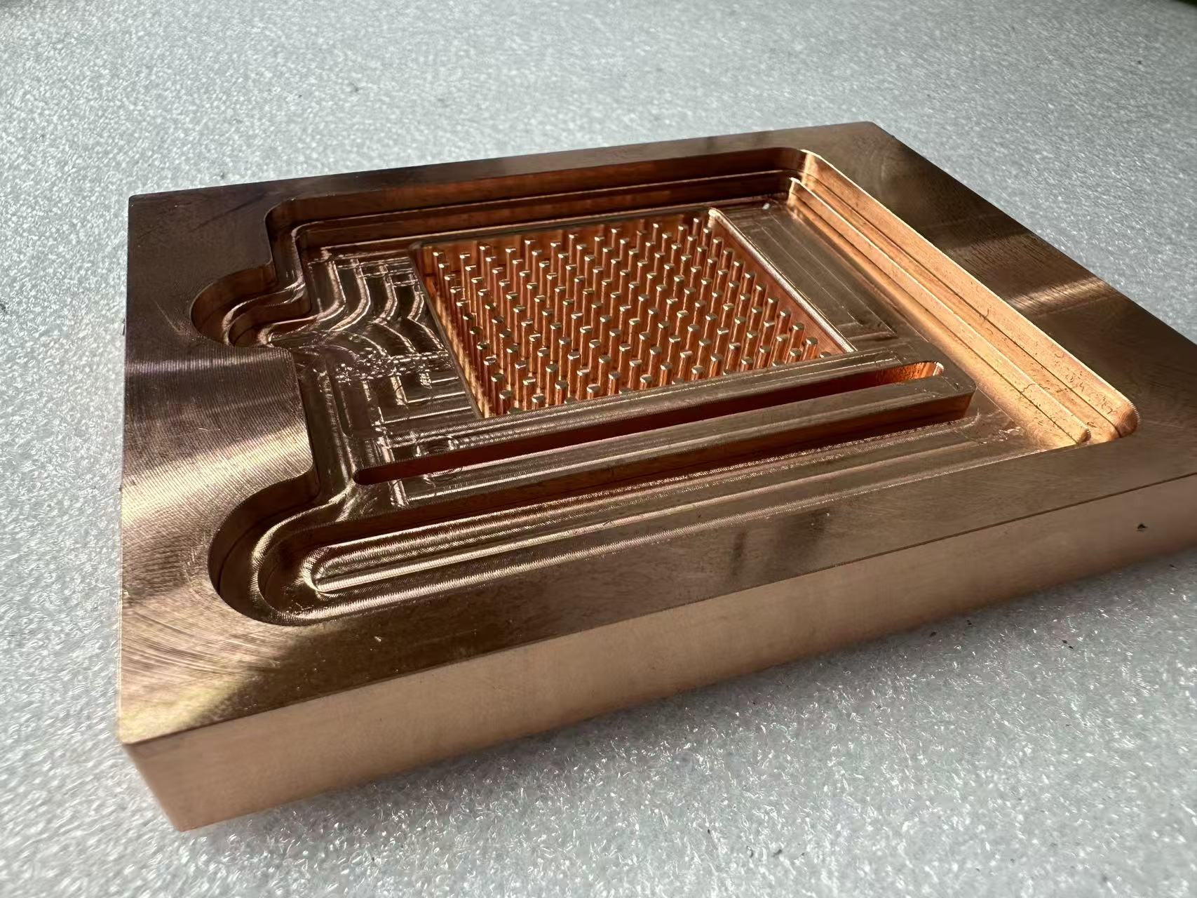
1. Micro-Channel: Preferred for ultra-high heat flux density applications.
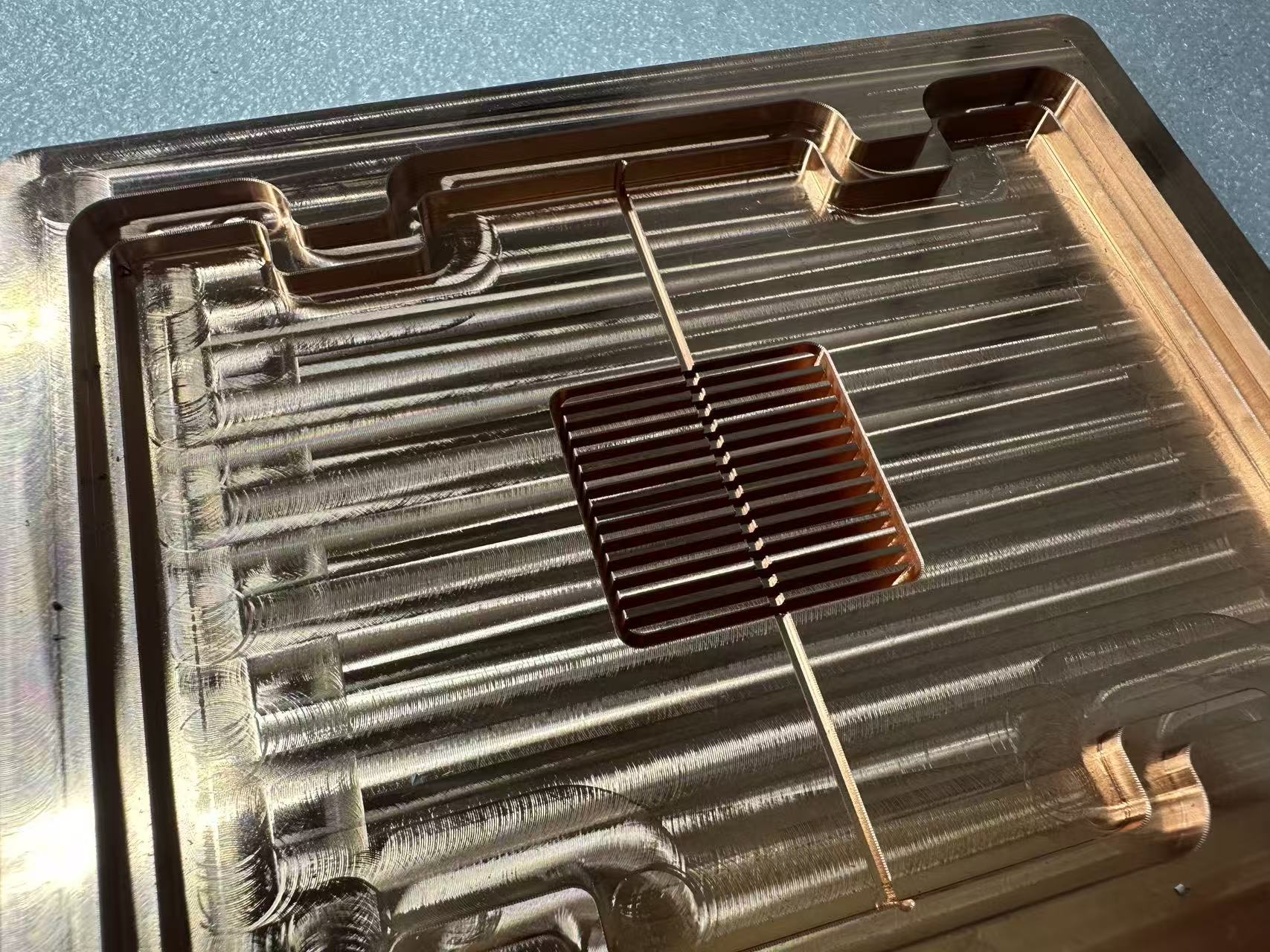
2. Meso Channel: Balanced solution for high performance and manufacturability.
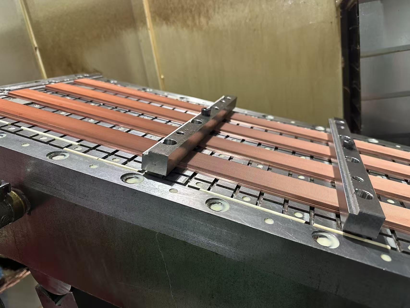
3. Internal Fin (Offset fin): Mature solution for medium-to-high power applications.
4. Machined Passage: Cost-effective solution for medium-to-low power applications.
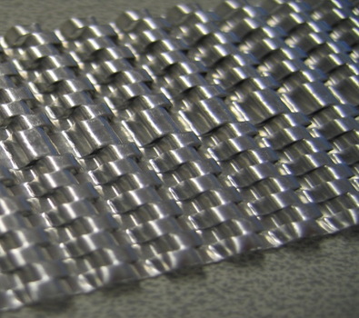
5. Pressed Tube: Ultra-low-cost solution for very low power applications.
III. Performance Curve Analysis and In-Depth Interpretation of Structural Characteristics
1. Overall Performance Trend and Key Insights
From the test curves, it is clear that the heat dissipation power of all five structures increases with rising coolant flow rate. This trend aligns with the basic principles of convective heat transfer: higher flow enhances fluid turbulence, disrupts the fluid boundary layer, increases the heat transfer coefficient between the fluid and the cooling plate wall, and thus improves heat dissipation capacity. However, performance gains vary significantly across structures, mainly due to differences in flow channel design rationality and heat transfer area.
Key insight: Higher flow is not always better. Excessive flow increases system pumping power and energy consumption. Therefore, selection must balance heat dissipation requirements and system energy consumption to find an optimal trade-off between thermal performance and pumping cost. For example, micro-channels show obvious advantages at high flow rates but consume much more pumping power than other structures, making them suitable only for applications demanding extremely high heat dissipation efficiency with low sensitivity to energy use.
2. Detailed Performance of Each Structure (Based on Core Flow Rate of 3.79 L/min) As 3.79 L/min is a typical flow rate for industrial liquid cooling systems, the corresponding thermal data offers the most practical reference. Below is an in-depth interpretation of each structure, including thermal performance, structural characteristics, engineering application scenarios, and practical selection guidance.
(1) Micro-Channel – The Performance Benchmark for Ultra-High Power Density
• Core performance: At 3.79 L/min, heat dissipation power reaches approximately 181.4 W/cm², ranking first among the five structures. It maintains superior heat dissipation across the full flow range and is the only viable solution for ultra-high heat flux applications.
• Structure and mechanism: Internal channel dimensions are typically below 100 μm. The tiny channels greatly increase the specific surface area between the fluid and the plate wall while intensifying flow disturbance, resulting in a heat transfer coefficient 3–5 times that of conventional structures, enabling rapid removal of heat from ultra-high power density sources.
• Engineering considerations and applicable scenarios: Micro-channels offer exceptional heat transfer efficiency but also clear drawbacks: high manufacturing difficulty relying on micro/nano processing, challenging mass production, and high cost; tiny channels lead to high pressure drop and demanding pumping requirements; strict coolant purity is needed to avoid clogging, raising maintenance costs. Thus, micro-channels are only recommended for extreme high-power-density fields such as advanced semiconductors, high-performance servers, and laser devices, supported by complete coolant filtration and high-power pumps. They are not advised for general industrial projects.
(2) Meso Channel – The Golden Compromise for Industrial Applications
• Core performance: At 3.79 L/min, heat dissipation power is around 150.4 W/cm², second only to micro-channels. At a low-to-medium flow rate of 1.90 L/min (0.5 GPM), it achieves 120.9 W/cm², nearly matching the high-flow performance of internal offset fins, showing excellent performance and flow adaptability.
• Structure and mechanism: Channel dimensions range from 100 μm to 1 mm, between macro channels and micro-channels. It retains specific surface area and heat transfer efficiency close to micro-channels while avoiding high pressure drop and clogging issues caused by overly fine channels, achieving a balanced performance and manufacturability.
• Engineering considerations and applicable scenarios: Meso channels represent an optimal solution for industrial high-power-density applications. They can be produced via conventional precision CNC machining or etching without micro/nano equipment, enabling manageable mass production and cost; better anti-clogging performance and higher tolerance to coolant impurities reduce maintenance; moderate pressure drop matches standard pumping systems without upgrades. Suitable applications include NEV IGBT modules, industrial high-power devices, and high-end medical equipment, balancing thermal performance and project economics.
(3) Internal Fin (Offset Fin) – A Mature and Reliable Choice for Medium-to-High Power
• Core performance: At 3.79 L/min, heat dissipation power is approximately 120.9 W/cm², with stable performance and gentle response to flow changes, ensuring consistent heat dissipation without precise flow control.
• Structure and mechanism: Internal fins significantly enhance heat transfer. The offset arrangement breaks laminar boundary layers and creates continuous turbulence, boosting the convective heat transfer coefficient by 30%–80% compared with straight fins. With high technological maturity and reliability, it is one of the most widely used liquid cooling plate structures in industry.
• Engineering considerations and applicable scenarios: Key strengths are stability, reliability, and versatility. Moderate manufacturing processes result in lower costs than micro- and meso-channels, with no complex system requirements. Ideal for medium-to-high power projects needing high heat dissipation but unable to accept the cost and complexity of micro/meso channels, such as general industrial power devices, NEV auxiliary cooling modules, and mid-range servers. Limitation: lower thermal efficiency ceiling than micro- and meso-channels, unable to satisfy ultra-high power density demands.
(4) Machined Passage – The Most Cost-Effective Solution for Medium-to-Low Power
• Core performance: At 3.79 L/min, heat dissipation power is roughly 60.5 W/cm², about one-third that of micro-channels. Moderate performance meets medium-to-low power density cooling requirements.
• Structure and mechanism: Simple flow channels are formed via CNC milling or stamping. Design is flexible with customizable shape and size, but limited heat transfer area results in much lower efficiency than micro-channels, meso-channels, and internal fins.
• Engineering considerations and applicable scenarios: Main advantages are simple processing, low cost, no complex equipment, and high production efficiency. Suitable for cost-sensitive medium-to-low power density projects including general electronics, low-power sensors, and consumer appliances. In engineering selection, if heat flux is below 60 W/cm² and cost is critical, machined passages are optimal, satisfying cooling needs while minimizing project expense. Limitation: insufficient heat dissipation for medium-to-high power scenarios.
(5) Pressed Tube – An Entry-Level Scheme for Extremely Low Power

• Core performance: At 3.79 L/min, heat dissipation power is approximately 24.0 W/cm², the lowest among the five structures, supporting only very low power density cooling. • Structure and mechanism: Extruded tubes are directly embedded into the cooling plate body. The process is extremely simple without complex channel machining, only requiring tube fixation, making it the lowest-cost solution tested.
• Engineering considerations and applicable scenarios: Positioned as an ultra-low-cost option, suitable for extremely low-power applications needing only basic heat dissipation, such as consumer electronics, low-power components, and small auxiliary cooling parts. Note the very low thermal limit: this structure must be rejected if heat flux exceeds 24 W/cm² to prevent overheating failure. Additionally, lower structural stability makes it unsuitable for long-term high-load operation.
V. Engineering Practical Selection Recommendations (Supplemented by Industry Pain Points)
Combined with test data, structural characteristics, and years of practical experience in industrial thermal design, clear selection recommendations are provided for different heat flux densities, flow constraints, and cost targets. Meanwhile, common industry selection misunderstandings are avoided to ensure the selected scheme is implementable.
1. Selection by Heat Flux Density
• Heat flux density > 150 W/cm²: The only choice — Micro-Channel. A high-flow, high-purity coolant system is required. Additionally, evaluate pumping power costs and manufacturing difficulty to prevent heat dissipation failure due to insufficient system support.
• Heat flux density 120~150 W/cm²: The optimal choice — Meso Channel. It balances high performance and manufacturability, does not require micro/nano processing equipment, controls system costs, adapts to most industrial high-power scenarios, and has much higher cost-effectiveness than micro-channels.
• Heat flux density 60~120 W/cm²: Flexible choices — Internal Fin (Offset Fin) or Machined Passage. Choose internal fins for heat dissipation stability and versatility; choose machined passages for cost control when extreme heat dissipation efficiency is not required.
• Heat flux density < 60 W/cm²: Cost priority — Machined Passage or Pressed Tube. Select machined passages for general medium-to-low power scenarios; select pressed tubes for extremely low-power and cost-sensitive scenarios to avoid cost waste caused by over-design.
2. Selection by System Flow Constraints (Practical Supplement)
• System flow rate ≥ 3.79 L/min: The performance advantages of Micro-Channel and Meso Channel can be fully exerted, suitable for high-power density projects. If cost permits, prioritize Meso Channel to balance performance and economy.
• System flow rate 1.90~3.79 L/min: Recommend Meso Channel or Internal Fin. Meso Channel can still maintain high heat dissipation performance in this flow range, with lower pressure drop than micro-channels; Internal Fin has stable performance, does not require precise flow control, and has stronger adaptability.
• System flow rate < 1.90 L/min: Micro-Channel is prohibited. Its high pressure drop will lead to excessive system pumping power, increased energy consumption, and even heat dissipation bottlenecks. Prioritize Meso Channel or Internal Fin to balance heat dissipation performance and system stability.
VI. Conclusions and Industry Outlook
Under the standardized test condition of ΔTfluid = 30℃, the heat dissipation performance of the five liquid cooling plate structures shows a clear echelon distribution. Combined with heat flux density, flow constraints, and cost targets, selection decisions can be made quickly.
The core selection logic for thermal design engineers should be “adapting to needs and balancing costs” rather than blindly pursuing high performance or low costs. By combining the actual heat load, flow conditions, and budget of the project, selecting the structure that best fits the needs can achieve the goals of “meeting heat dissipation standards, controlling costs, and ensuring stable operation”.