| Performance Metric | Target Value / Condition |
|---|---|
| Total Chip Power | 2700W for the GB200 (1x Grace CPU + 2x B200 GPUs) |
| Heat Flux Density | Exceeding 50W/cm², reaching 150W/cm² in some spots |
| Temperature Rise Limit (Tc) | Under 40°C for the chip, and under 30°C for the GPU |
| Required Thermal Resistance | Extremely low, less than 0.03°C/W |
| Required Flow Resistance | Not exceeding 20kPa |
Next-generation AI chips like NVIDIA’s GB200 are pushing the limits of performance. But this power comes at a cost: incredible heat. A single GB200 chip package can draw a massive 2700 watts. With so much power in a small space, traditional air cooling is no longer enough. The only way to keep these chips cool is with advanced liquid cooling.
Let’s break down the exact engineering challenges and see how Kenfa Tech designs a liquid cooling cold plate to handle the extreme heat of the GB200.
The Numbers Behind the GB200’s Cooling Challenge
To appreciate the solution, we must first understand the problem in detail. The heat from the GB200 isn’t just high; it’s also incredibly concentrated. This is called heat flux density.
The chip produces a heat flux of more than 50W/cm²—that’s 50 watts of heat in an area the size of a pinky fingernail. In some hotspots, this can spike to an intense 150W/cm². If not managed, this heat would quickly damage the chip. So, the chip’s temperature rise (Tc) must be kept below 40°C in general, with the GPU itself requiring an even stricter limit of under 30°C.
Meeting these numbers requires a cooling system with two key characteristics:
- Extremely low thermal resistance (less than 0.03°C/W). This means the cold plate is super-efficient at pulling heat away from the chip.
- Low flow resistance (not exceeding 20kPa). This ensures the cooling liquid can move through the plate easily without needing a powerful, energy-hungry pump.
“We’re not just managing heat; we’re managing extreme heat density. The goal is to create a pathway for heat to escape as quickly and efficiently as possible. Every decimal point in the thermal resistance calculation matters for the stability of these powerful AI systems.”
– Industrial Thermal Engineer
Inside the Cold Plate: Structure and Flow Physics
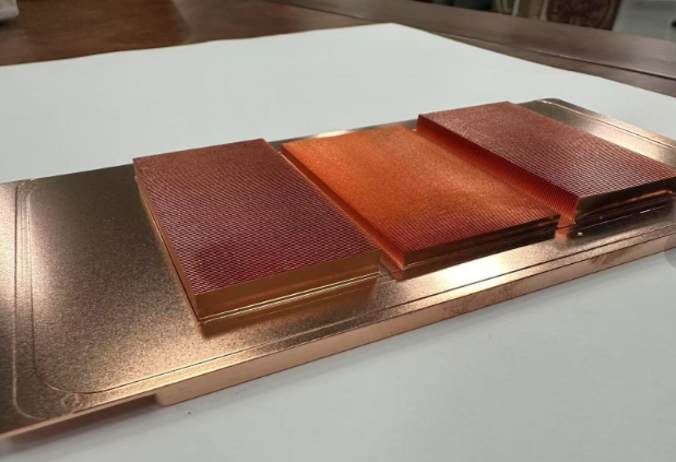
To achieve these impressive numbers, engineers use a specific design called a microchannel cold plate, often built with a skived fin process.
Microchannel Structure by Skived Fins
The cold plate is usually made from copper, a material that is excellent for heat transfer (with a thermal conductivity of 385W/mK). A special tool then shaves thin fins directly from the copper base. This creates a series of tiny, parallel channels.
- Fin thickness (t) is generally ≤ 0.5mm.
- The spacing between fins (P) is also ≤ 0.5mm.
- The fin height (L) is typically ≥ 3mm.
These tiny dimensions create a massive internal surface area, which is vital for pulling heat into the liquid coolant that flows through the channels.
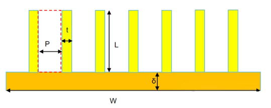
The structure of the microchannels is key. The relationship between fin height (L) and spacing (P) defines how the liquid flows.
Understanding the Flow Inside
The way liquid moves through these tiny channels is very important. Engineers analyze this using a few key formulas.
First, they calculate the channel’s hydraulic diameter (Dh), which represents the effective size of the channel for fluid flow. The formula is:
Dh = 2(P*L)/(P+L)
Because the fin height (L) is much larger than the spacing (P), with an L/P ratio often over 15, this formula simplifies to: Dh ≈ 2P. This tells us the effective channel size is directly related to the tiny spacing between fins.
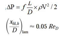
Next, engineers determine the type of flow using the Reynolds number (Re):
Re = ρ * V * Dh / μ
In this formula, ρ is the fluid density, V is the velocity, and μ is the viscosity. For a typical cold plate, the flow velocity (V) is usually less than 0.1m/s. When calculated, the Reynolds number (Re) is less than 2000. This confirms the flow is smooth and predictable, which is known as laminar flow.
How Engineers Improve Cold Plate Performance
Based on that science, engineers know exactly what to adjust to make the cold plate better. There are two main goals:
1. Reducing Flow Resistance
To make the liquid flow more easily, engineers can:
- Reduce the flow velocity (V) between the fins.
- Reduce the length of the fins in the direction of the flow.
2. Increasing Convective Heat Transfer
To make the plate cool more effectively, they need to increase the heat transfer coefficient (h). An interesting discovery is that for this type of laminar flow, the velocity (V) doesn’t have much effect on `h`. So, they have two other options:
- Increase the liquid’s thermal conductivity (k) by choosing a more effective coolant.
- Reduce the equivalent hydraulic diameter (Dh), which essentially means making the channels even smaller and tighter.
By using these precise principles and calculations, engineers can design and fine-tune an efficient liquid cooling plate. This careful work is essential for the future of AI, ensuring that powerful chips like the GB200 can operate at their full potential without overheating.