Thermal Management of High-Speed Motors: Requirements and Practice of Shell Liquid Cooling Heat Dissipation Solutions
The popularity of high-speed motors (typically defined as motors with a rotational speed ≥ 10000r/min) in industrial drives, new energy vehicles, aerospace, and other fields has made thermal management capability a core bottleneck restricting performance and lifespan. When a motor operates at high speeds, electromagnetic losses and mechanical friction losses of the stator and rotor increase nonlinearly. If heat cannot be dissipated promptly, it may cause insulation material aging and efficiency reduction at best, or winding burnout and other failures at worst. The shell liquid cooling method, with its high heat exchange efficiency, has become one of the mainstream thermal management solutions for high-speed motors.
I. Core Thermal Management Requirements for High-Speed Motors Under High-Speed Operation
The “high-speed” characteristic of high-speed motors directly amplifies the difficulty of thermal management, and its core requirements can be summarized in three points:
1. High Heat Exchange Efficiency
The power density of high-speed motors can be 2-5 times that of ordinary motors, resulting in extremely high heat generation per unit volume. Traditional air cooling solutions have a heat transfer coefficient of only 20-50W/(m²·K), which cannot handle instantaneous high heat; while liquid cooling solutions have a heat transfer coefficient of 500-2000W/(m²·K), which can quickly remove heat.
2. Temperature Uniformity
Components such as stator windings and bearings of high-speed motors are sensitive to temperature gradients: local overheating accelerates insulation layer failure, and excessive temperature differences in bearings can easily cause jamming. Liquid cooling systems can achieve uniform temperature distribution of the shell and internal components through flow channel design.
3. Lightweight and Compactness
High-speed motors are mostly used in scenarios sensitive to space and weight (such as drones and electric drive axles). Liquid cooling shells can integrate heat dissipation channels and motor housings, eliminating the need for additional cooling devices, and balancing heat dissipation and structural lightweighting.
II. Structure and Working Logic of Shell Liquid Cooling Heat Dissipation Solutions
The shell liquid cooling solution for high-speed motors mainly relies on housing flow channels + coolant circulation to achieve heat transfer. The typical structure and process are as follows:
1. Design of Liquid Cooling Shell
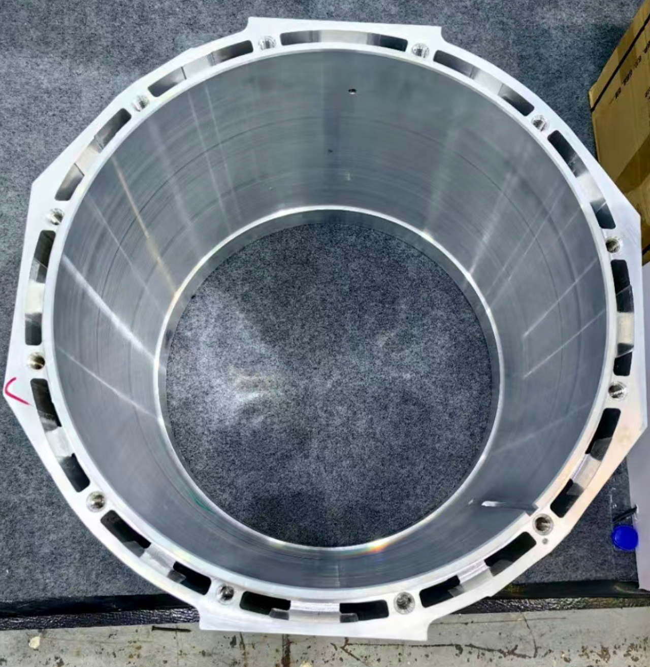
Aluminum alloys (such as 6061 and 7075) are usually used as the shell base material (balancing thermal conductivity and lightweighting). Spiral, serpentine, or parallel flow channels are machined inside the shell wall (the hollow/groove structure of the motor shell in the images serves as the carrier for these channels). Coolants (commonly ethylene glycol aqueous solution, silicone oil, etc.) flow in the channels and directly exchange heat with the shell.
2. Heat Transfer Path
Heat generated by internal losses of the motor → transferred from the stator core/winding to the inner wall of the shell → transferred from the shell wall to the coolant in the flow channel via thermal conduction → the coolant carries heat into an external cooling system (such as a radiator or chiller) for cooling and then circulates back.

III. Advantages and Practical Application Scenarios
Compared with air cooling, oil cooling, and other solutions, shell liquid cooling has particularly prominent advantages in high-speed motor scenarios:
• Adaptable to High Power Density: It can support the stable operation of high-speed motors with a power density ≥ 50kW/L;
• Low Noise: No mechanical noise from fan rotation, suitable for scenarios with high noise requirements (such as medical equipment and high-end machine tools);
• Strong Environmental Adaptability: Unaffected by external dust and humidity, usable under harsh working conditions.
Currently, this solution has been widely applied in:
• High-speed drive motors for new energy vehicles (such as the permanent magnet synchronous motor of Tesla Model 3);
• High-speed servo motors in the aerospace field;
• High-speed spindle motors in the industrial field (such as CNC machining centers).
IV. Optimization Directions of the Solution
The current shell liquid cooling solution can still be upgraded in the following ways:
1. Flow Channel Optimization: Use simulation (such as CFD) to design special-shaped flow channels, improving heat exchange efficiency while reducing flow resistance;
2. Material Upgrade: Use materials with high thermal conductivity (such as silicon carbide ceramics) to further enhance the thermal conductivity of the shell;
3. Intelligent Temperature Control: Equip with flow control valves and temperature sensors to realize dynamic adjustment of coolant flow, balancing heat dissipation and energy consumption.
Thermal management of high-speed motors is the key to breaking the “performance ceiling”, and the shell liquid cooling solution, with its high efficiency and compactness, has become the preferred solution for high-speed scenarios. As motor speed and power density continue to increase, the design and process of liquid cooling heat dissipation will continue to iterate, supporting more extreme high-speed motor applications.
Design Parameter List for Liquid-Cooled Shells of High-Speed Motors
This list covers key indicators such as core structure, materials, and heat dissipation performance, and can be directly used for scheme evaluation or selection:
I. Basic Structural Parameters
Inner diameter of the shell Matches the outer diameter of the motor stator (e.g., 50-300mm) An interference fit between the stator and the shell (for thermal conduction) is required.Flow channel type Spiral/serpentine/parallel flow channel Spiral channels have better temperature uniformity; parallel channels have lower flow resistance.Flow channel cross-section size Width 8-20mm, depth 5-15mm A balance between heat exchange area and flow channel pressure loss is needed.Number of flow channels 4-12 (depending on the shell size) More channels improve heat exchange efficiency but increase flow resistance.Installation interface size G1/4-G1/2 threaded interface Compatible with quick connection of coolant pipelines
II. Material Parameters
Material Type Key Performance Parameters Application Scenarios
Aluminum alloy (6061-T6) Thermal conductivity 167W/(m·K), density 2.7g/cm³ General scenarios (high cost-effectiveness)
Aluminum alloy (7075-T6) Thermal conductivity 130W/(m·K), higher strength Scenarios with high structural strength requirements (e.g., aerospace)Cast aluminum (ADC12) Thermal conductivity 96W/(m·K), suitable for casting complex flow channels Mass-produced medium and low-power high-speed motors
III. Heat Dissipation Performance Parameters
Parameter Item Typical Range Test Conditions,Maximum heat dissipation power 5-50kW Coolant flow 5-20L/min, inlet temperature 25℃
Heat transfer coefficient 800-1800W/(m²·K) Calculated based on convective heat exchange between the shell and coolant.Shell temperature uniformity ≤5℃ (maximum difference) Measured after 30 minutes of full-load motor operation.Coolant pressure loss ≤0.2MPa Flow channel resistance at rated flow.
IV. Adaptable Motor Parameters
Motor Type Adaptable Range
Motor speed 10000-60000r/min
Motor power density 20-80kW/L
Motor rated power 5-200kW
Customized Parameter Table for Liquid-Cooled Shells of High-Speed Drive Motors for New Energy Vehicles
Suitable for: Pure electric passenger cars/small SUVs;
Motor type: Permanent magnet synchronous high-speed motor)
Parameter Category Specific Parameter Item Customized Indicator Design Description

Structural Adaptation Inner diameter of the shell 180-220mm Matches the stator outer diameter of mainstream 150-200kW drive motors
Flow channel type Spiral + segmented parallel composite flow channel Balances temperature uniformity of stator teeth/yoke and reduces flow resistance
Flow channel cross-section size Width 12mm, depth 8mm Adapted to the rated flow of on-board coolant pumps (8-12L/min)
Installation interface G3/8 quick-connect interface + O-ring seal Meets sealing requirements in the vibration environment of on-board pipelines
Material and Process Base material 6061-T6 aluminum alloy (forged) Forging process improves shell strength to adapt to chassis vibration conditions
Surface treatment Anodization (film thickness 15-20μm) Enhances corrosion resistance to adapt to complex on-board environments
Heat Dissipation Performance Maximum heat dissipation power 35-45kW Covers heat dissipation needs under motor peak power (200-250kW)
Heat transfer coefficient 1200-1600W/(m²·K) Coolant is 50% ethylene glycol aqueous solution, inlet temperature 40℃
Maximum shell temperature ≤120℃ (motor peak load for 30s) Ensures a safety margin for stator insulation materials (temperature resistance 155℃)
Coolant pressure loss ≤0.15MPa Adapted to the output pressure of on-board electronic water pumps (≤0.3MPa)
Adaptable Motor Parameters Motor speed 12000-18000r/min High-speed range of mainstream hairpin motors
Motor power density 40-60kW/L Current design direction of “miniaturization and high integration” for automakers
Kenfa Tech can provide you with design and product support, including our existing molds, to save you development time and costs.