After determining parameters such as material, coolant, thermal resistance, and flow distribution, the design of an AI liquid cooled plate is far from complete. To ensure the stable, efficient, and long-term operation of the cold plate in practical systems, it is necessary to focus on solving the following three key technical issues:
1) Flow resistance optimization: Ensure that the coolant can flow through the cold plate at sufficient flow rate to meet heat dissipation requirements and avoid insufficient system flow.
2) Pressure resistant design: prevents the cold plate from deforming under operating pressure, leading to serious problems such as sealing failure (leakage) and poor adhesion with the heating chip (increased thermal resistance).
3) Long term operational reliability: Ensuring stable and non deteriorating performance of the cold plate during its service life, with the core being to prevent fin blockage, corrosion, and scaling.
This article will focus on these three aspects, providing design optimization ideas and practical suggestions.
Optimization of Cold Plate Flow Resistance
Goal: Reduce flow resistance and ensure that the system flow meets the cooling requirements.
Challenge: As the power of GPU/ASIC chips exceeds 1000W and the power density increases (~150W/cm ²), thinner fins (gap ≤ 0.15mm) need to be used, resulting in a significant increase in cold plate flow resistance.
1.1 Conventional solutions and limitations:
Traditional design: One side of the fin receives liquid and the other side receives liquid.
Applicable conditions: When the fin gap is ≥ 0.2mm, the flow resistance is relatively low (usually<10kPa), which is acceptable.
Problem: When the fin gap is ≤ 0.15mm, the flow resistance of this scheme is too high.
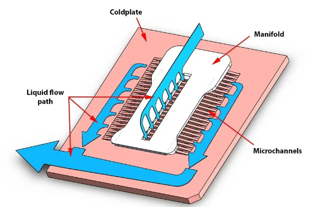
1.2 Optimization Plan: Top Inlet, Two Sides Outlet Principle: The flow between the cold plate fins is usually laminar, and the flow resistance △ P is approximately proportional to the flow velocity V and fin length L, △ P ∝ K * V * L
Details of the plan:
Move the inlet directly above the fin area.
Set up liquid outlets on both sides of the fin area.
Optimization effect:
The length of the flow path L is halved (equivalent to changing from a single end to a central flow direction).
Under the same total flow rate, the flow velocity V through the fins is halved.
Therefore, the flow resistance △ P in the fin area is reduced to about 1/4 of the single-sided inlet and outlet scheme.
Advantages: Significantly reduce the flow resistance of high power density and small fin gap cold plates, ensuring system flow.
So, the 1-in-2-out flow channel designed by our Kenfa Tech engineers can solve the problem of excessive flow resistance in AI liquid cooling plates.
Cold plate pressure resistance improvement
To prevent deformation of the cold plate under pressure when the cold plate substrate is extremely thin (1-2mm), ensuring reliable sealing and good contact with the chip.
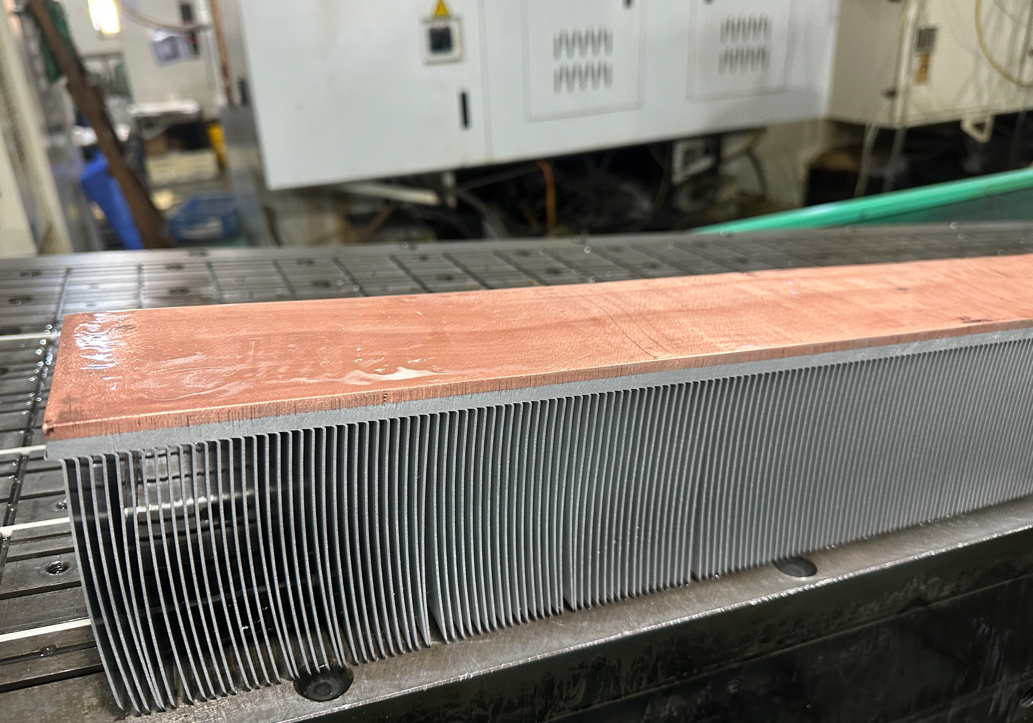
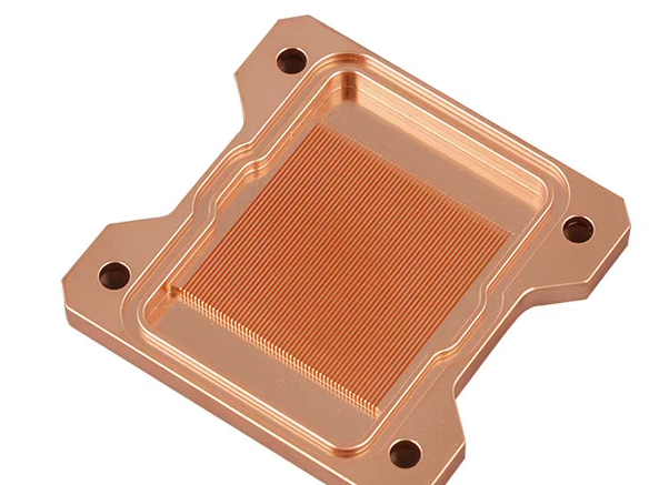
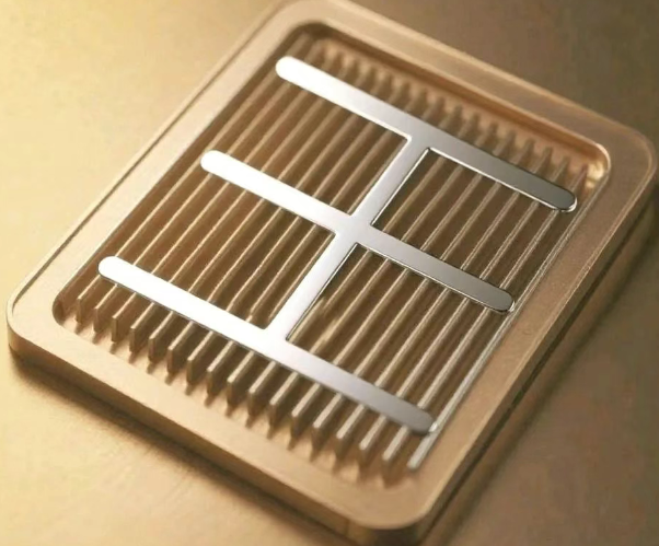
Conventional structural issue: Typical copper shovel tooth cold plate: The top of the fins is not welded to the cover plate.
Mechanical model: equivalent to a flat plate with dimensions of length (a) x width (b), with edges constrained and subjected to uniformly distributed pressure (P).
Pressure resistance theory (classical shell theory):
Formula for maximum allowable pressure: P=β * σ * (t/b) ²
P: Pressure (MPa)
σ: Allowable stress of material (MPa)
t: Cover plate thickness (mm)
b: Plate width perpendicular to the reinforcement direction (mm) – critical dimension
β: Shape factor (depending on aspect ratio a: b)
Formula for required cover thickness: t=b * √ (β * P/σ)
Shape factor β (influence of aspect ratio a: b):
1:1,β=0.307
2:1,β=0.497
3:1,β=0.616
4:1,β=0.697
6:1,β=0.750
So, when determining the size (a x b) of the cold plate fin area, reducing the width b can significantly improve the maximum pressure resistance P. Adding middle reinforcement ribs: adding support structures in the middle of the fin area. Weld the cold plate substrate, reinforcement ribs, and cover plate into a rigid structure as a whole. (Leave a gap of 0.05~0.1mm between the fins and the cover plate). Effect: Effectively reduces the critical dimension b (which becomes the spacing between reinforcement ribs) when calculating pressure resistance, greatly improving the pressure resistance capability. At the same time,Top Fin Welding:Weld the top of the fins to the cover plate as a whole.The effect:The use of dense micro channel fins as support points greatly enhances the structural stiffness and deformation resistance.When the craftsmanship is excellent, the use of reinforcing ribs can be replaced or reduced.Significantly improve the pressure resistance capability.
Long term reliability of cold plate operation
Prevent performance degradation (increase in thermal resistance, decrease in flow rate, leakage) and ensure long-term stable operation. Metal debris, assembly foreign objects, corrosion products, and scale/biofilm deposits in the small fin gaps, hindering flow and heat transfer. Copper undergoes slow and uniform thinning in pure water. Localized corrosion: More harmful, including erosion corrosion (significantly accelerated at flow rates exceeding 1.5m/s), microbial corrosion
Acid corrosion. Consequences: leading to thinning of fins, decreased strength, seal failure (leakage), and performance degradation. At the same time, it is also prone to scaling, with inorganic scales such as calcium carbonate (CaCO3), magnesium carbonate (MgCO3), and biofouling depositing on the surface of the fins. Significantly increase heat transfer resistance and reduce heat dissipation performance.
We at Kenfa Tech typically provide customers with design solutions and recommendations that ensure system configuration with an over precision of ≤ 50 μ m (300 mesh) to filter out large particles such as metal debris and welding slag
All components are cleaned before leaving the factory to ensure that there are no large particle residues, and all pipeline interfaces are equipped with end caps for sealing. At the same time, water quality is controlled, and pH<9 values should be well controlled and monitored. Corrosion inhibitors<10ppm, fungicides<12ppm, sulfides<15ppm, sulfates<100ppm, chlorides<50ppm, and conductivity<0.2-20us/cm are added to the coolant according to the proportion.
Conclusion:
The reliability design of AI liquid cooling plates is a key link in the success of high-performance heat dissipation systems, and is not a simple extension of performance calculations. This article explores three core dimensions:
1) Flow resistance optimization: In response to the problem of increased flow resistance caused by narrowed fin gaps under high power density, an optimization scheme of “top inlet and two side outlet” was proposed and demonstrated. This scheme can significantly reduce the pressure drop in the microchannel area to about 1/4 of the traditional single-sided inlet and outlet scheme by halving the effective flow path length and flow velocity
2) Pressure resistance enhancement: Based on the classical shell theory, the decisive effects of cover thickness (t), critical width (b), material allowable stress (σ), and aspect ratio (β) on the maximum pressure resistance (P) of the cold plate have been clarified. Two effective engineering solutions have been proposed: adding intermediate reinforcement ribs and using tooth top welding technology. The former improves the pressure resistance by reducing the critical dimension b, while the latter utilizes the fins themselves and the cover plate to form an integrated support structure, which is the preferred solution for improving stiffness and pressure resistance
3) Long term operational reliability: Systematically identified three major risks that threaten long-term reliability: blockage, corrosion, and scaling. To control these risks, strict water quality control must be implemented for the circulating coolant (TCS) inside the cold plate, with standards much higher than those for primary water (FWS). According to the ASHRAE guidelines, technical requirements for key water quality parameters (pH, corrosion inhibitors, fungicides, ion concentration, suspended solids, microorganisms, etc.) are detailed.
Only through careful design and strict control in these three dimensions can the cold plate maintain excellent heat dissipation performance, structural integrity, and system stability during high load and long-term operation, providing reliable cooling guarantee for high-power electronic devices.