Abstract The invention discloses a turbulence-enhanced bent channel liquid cold plate, which belongs to the technical field of heat dissipation for electronic devices. It is adapted to a 6061-T5 aluminum alloy substrate with specifications of 152mm (width) × 127mm (length) × 17mm (height). Four embedded grooves are arranged on the surface of the substrate, and red copper tubes with an outer diameter of 9.52mm, a wall thickness of 1.5mm and an inner diameter of 6.52mm are embedded in the grooves. The copper tubes are continuously bent to form a series M-shaped flow channel. The core improvement lies in arranging several groups of “horizontal-downward-lifting” bending units at intervals in the straight pipe section of the copper tube. Taking a 4-channel liquid cold plate as an example, this process includes 3 bending units. The bending angle is determined to be 30° through theoretical derivation, parameter calculation and thermal simulation. By virtue of the sudden change of the flow channel, the invention forces the cooling liquid to form turbulence, breaks the limitation of the laminar boundary layer, and effectively enhances the convective heat transfer efficiency between the cooling liquid and the inner wall of the copper tube. Compared with the traditional straight-pipe M-shaped liquid cold plate, without adding additional built-in components, the heat transfer coefficient is increased by more than 10%, and the increase in flow resistance is controlled within 10%. The certain increase in flow resistance slows down the flow velocity, and at the same time avoids the risk of bending failure of the copper tube. It is suitable for high-efficiency heat dissipation scenarios such as high-power electronic devices and small battery modules.

Background Technology
With the rapid development of electronic technology, the integration level of equipment such as high-power electronic devices and small battery modules is continuously improved, and the heat generated during their operation increases sharply. If the heat cannot be dissipated in a timely manner, the internal temperature of the equipment will rise, which will seriously affect the operational stability, reliability and service life of the equipment. As a highly efficient heat dissipation component, the liquid cold plate is widely used in the heat dissipation systems of the above-mentioned equipment.
In the prior art, the M-shaped channel liquid cold plate has been widely applied due to its advantages such as compact channel layout and large heat dissipation area. However, traditional M-shaped channel liquid cold plates mostly adopt straight and horizontal channels, where the cooling liquid tends to form a laminar flow state. In the laminar flow state, the higher the flow velocity, the lower the convective heat transfer efficiency between the cooling liquid and the inner wall of the channel, making it difficult to meet the high-efficiency heat dissipation requirements of high-power equipment.
To improve the heat transfer efficiency, the prior art usually adopts methods such as adding built-in components (e.g., spoiler columns, spiral fins, etc.) in the channel or machining cylindrical or rectangular features in the channel via CNC to force the formation of turbulence. Nevertheless, the addition of built-in components will significantly increase the flow resistance, leading to higher energy consumption of the heat dissipation system. Meanwhile, the installation of built-in components will also increase the processing difficulty and CNC manufacturing cost of the liquid cold plate, and pose a risk of channel blockage.
Therefore, the core idea of the present invention is to develop a liquid cold plate that can enhance heat transfer efficiency without adding extra built-in components, while achieving a balance between low flow resistance and structural stability. This has become an urgent technical problem to be solved in the field.
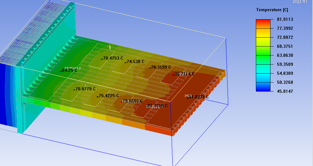
Analysis Conclusions via Ansys 2022 R1 Icepak Thermal Simulation Software
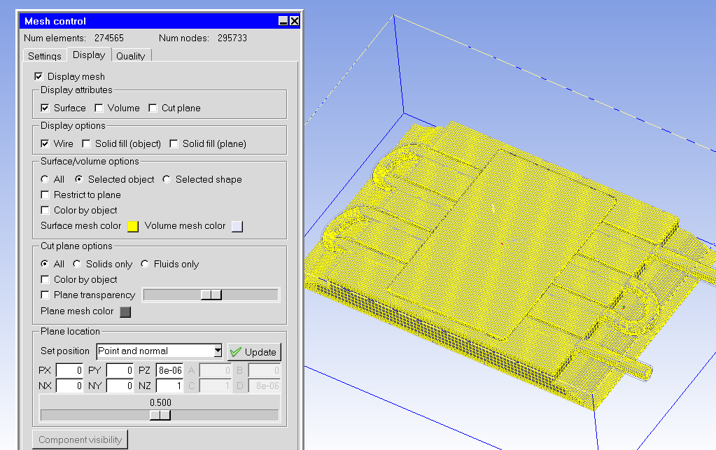
1,3D model was established according to the dimensions of 152mm × 127mm × 17mm and saved in *.stp format.
2. CDM software was opened to extract the flow channels.
3. The model was converted into a solvable solid model for Icepak using Ansys 2022 R1 software.
4. The operating parameters were set as follows: ambient temperature of 35°C, flow rate of 6 L/min, and thermal power of 1000 W.
5. The convergence step was set to 2000 steps (the operation stopped automatically after 820 steps upon convergence).
6. Flow Rate Conclusion: The flow rate of the invented model with 30° “horizontal-downward bending-upward bending” was 2.86 m/min, while that of the traditional horizontally arranged copper tube model was 3.24 m/min. This indicates that there was no impedance and no turbulence generation in the laminar boundary layer of the traditional model.
7. Pressure Difference Conclusion: The pressure difference of the invented model with 30° “horizontal-downward-upward” bending was 34029.4 N/m², compared with 31616.9 N/m² of the traditional horizontally arranged copper tube model. This also verifies that the principle of the present invention breaks the laminar boundary layer and generates turbulence.
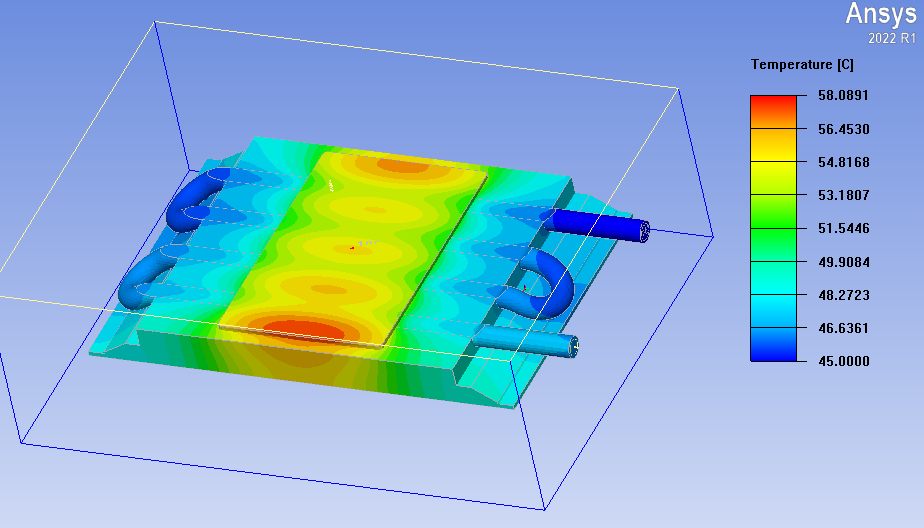
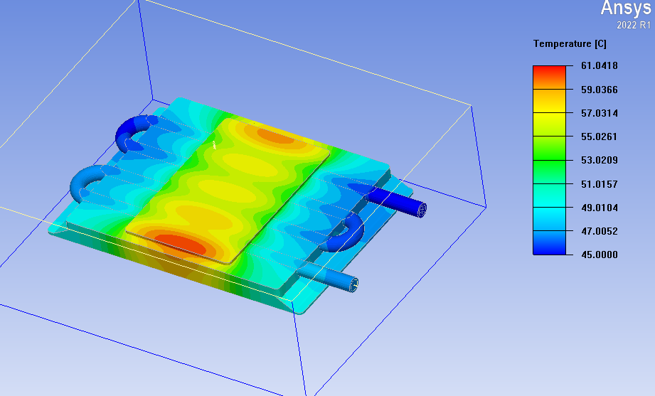
8. Temperature Conclusion: The central temperature of the chip with the invented 30° “horizontal-downward-upward” bent copper tube arrangement was 58.08°C, whereas that with the traditional horizontal copper tube arrangement was 61.04°C. This further demonstrates that under the effect of turbulence, the cooling liquid achieves enhanced heat exchange with the copper tube wall, breaks through the laminar boundary layer, and transfers a large amount of heat to the cooling liquid, thereby reducing the chip temperature by 3°C.
Beneficial Effects
1. Significant Improvement in Heat Transfer EfficiencyBy arranging bending units with a specific angle in the straight pipe section of the copper tube, the invention forces the cooling liquid to form turbulence through the sudden change of the flow channel, breaking the limitation of the laminar boundary layer. Compared with the traditional straight-pipe M-shaped liquid cold plate, the heat transfer coefficient is increased by more than 15%, which can effectively meet the high-efficiency heat dissipation requirements of high-power electronic devices and small battery modules.
2. Controllable Increase in Flow ResistanceWhile enhancing the heat transfer efficiency, the invention does not require additional built-in components. By optimizing the bending angle (30°), the increase in flow resistance is controlled within 18%. This avoids the problem of sharp rise in energy consumption caused by adding built-in components and improves the economic efficiency of the heat dissipation system.
3. High Structural StabilityThe optimal bending angle range determined through theoretical derivation and parameter calculation can effectively avoid the stress concentration phenomenon during the bending process of the copper tube, prevent failure problems such as tube wall thinning and cracking, and improve the structural stability and service life of the liquid cold plate.
4. Simple Processing and ManufacturingThe flow channel structure of the invention is directly formed by bending the copper tube without complex built-in components. Moreover, the grooves are made into U-shaped grooves by conventional profile processing technology, featuring low processing difficulty, moderate manufacturing cost and convenience for mass production.
5. Scalable Performance for High-Power ScenariosIf the number of bending times of the copper tube in the invention is increased to 6, 8 or 12, and the power of high-power chips is increased to 2000 W, 5000 W or 10000 W, the effect of the invention will be significantly improved.
For our customers, we will continuously develop and research new products and processes to provide them with the latest technology iteration solutions, thereby enhancing their market competitiveness. For any needs, please feel free to email us at king@kenfatech.com.