The Importance of Thermal Interface Materials in Thermal Management: Understanding the Key Selection Logic from a Thermal Analysis Case of High-Power Equipment

With the continuous increase in the power density of electronic devices, heat dissipation issues of high-power chips and industrial power modules have become a core bottleneck restricting equipment reliability. The primary goal of thermal management is to efficiently transfer heat generated by heat sources (such as chips) to heat dissipation structures (such as water-cooled plates) for removal. As the connecting medium between the two, thermal interface materials (TIMs) directly determine the efficiency of heat transfer. Improper selection will not only fail to assist heat dissipation but also form a “thermal resistance barrier”. Starting from the essential function of TIMs, this article uses a thermal analysis case of a 2425W power equipment to analyze the core problem of “heat dissipation failure caused by incorrect TIM selection” and clarify the key selection logic of TIMs in thermal management.
1. Re-recognizing Thermal Interface Materials: It’s Not “Having One Is Enough”, But “Choosing the Right One Matters”
Most people believe that “as long as TIMs are used, heat dissipation can be assisted”. However, the fact is that the core value of TIMs lies in “reducing interface thermal resistance” rather than simply “filling gaps”. If the material itself has poor thermal conductivity, it will instead become an “obstacle” to heat transfer.
In electronic devices, even after precision processing, the contact surface between the chip and the Liquid cooling plate still has micro-scale uneven gaps. The air in these gaps (with a thermal conductivity of only 0.026W/(m·K)) forms a natural “thermal resistance”. An ideal TIM should be able to squeeze out air, fit the contact surface, and build a “low-resistance thermal channel” with its high thermal conductivity, allowing heat from the chip to be quickly transferred to the water-cooled plate. However, if the selected material has low thermal conductivity and excessive thickness, the “material thermal resistance” it forms will be superimposed with the interface thermal resistance, which instead hinders heat transfer. This is the core reason why many devices “still have poor heat dissipation even with TIMs installed”.
2. Thermal Analysis Case of 2425W Power Equipment: The “Negative Effect” of Choosing the Wrong TIM
To intuitively demonstrate the importance of TIM selection, we take a thermal analysis project of a 2425W high-power equipment as an example to analyze the specific problem of “heat dissipation failure caused by low-performance TIMs”:
2.1 Basic Parameters of the Case
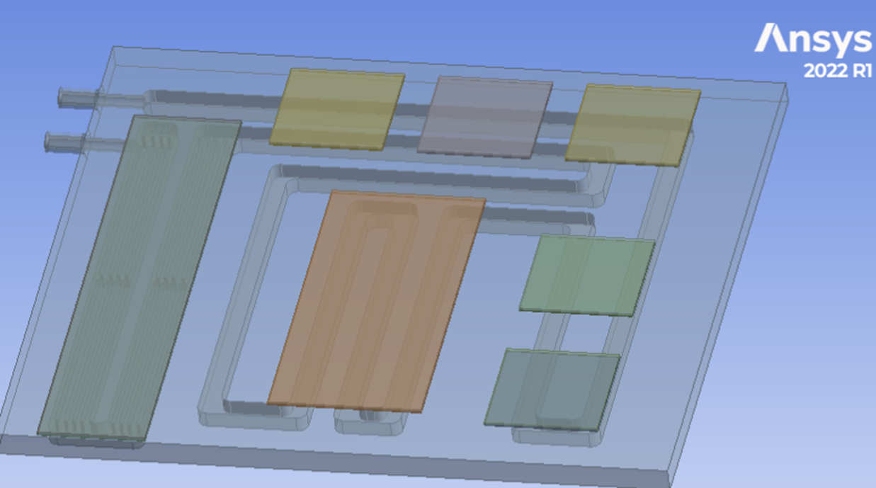
•Total equipment power: 2425W (the core consists of 4 groups of high-heat-generating chips, which require rapid heat dissipation through a water-cooling system)
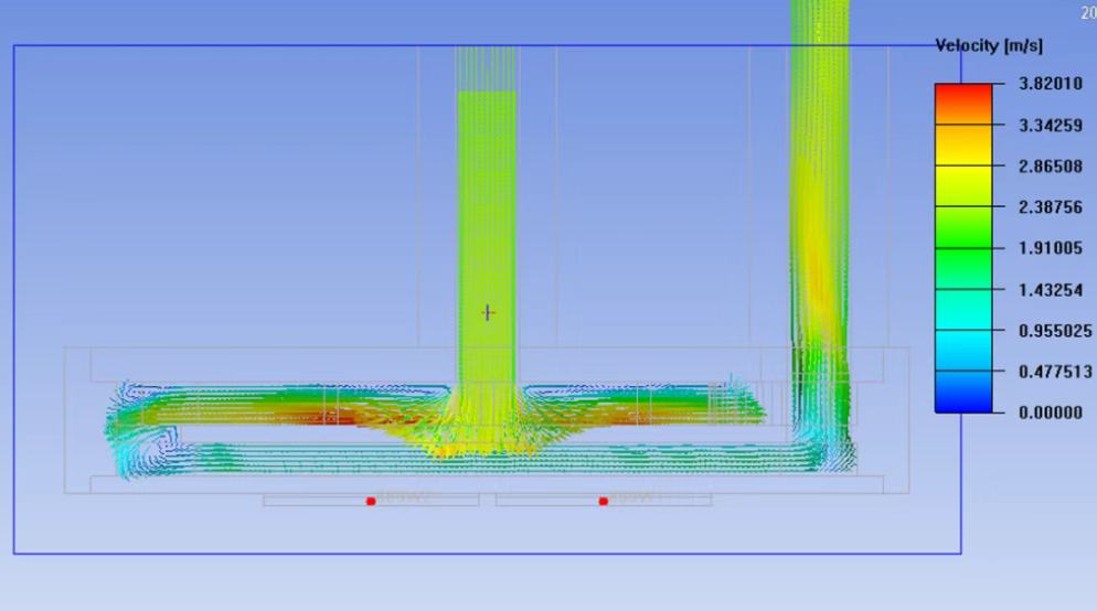
•Heat dissipation configuration: Water-cooling system (coolant is 50% pure water + 50% ethylene glycol, with a flow rate of 5L/min, ensuring sufficient heat dissipation capacity of the water-cooled plate itself)
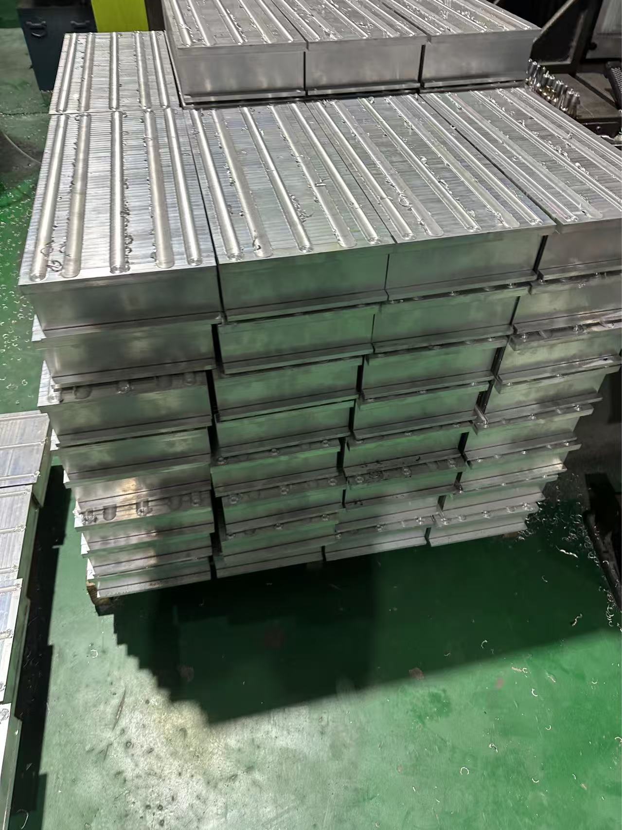
•Water-cooled plate process: Friction stir welding (to avoid local uneven thermal conductivity caused by structural defects of the water-cooled plate itself)
•Thermal interface material: A thermal pad with a thickness of 0.5mm and a thermal conductivity of 3.0W/(m·K) (the core variable for subsequent problems)
2.2 Thermal Analysis Results: TIM Becomes the “Thermal Resistance Bottleneck”
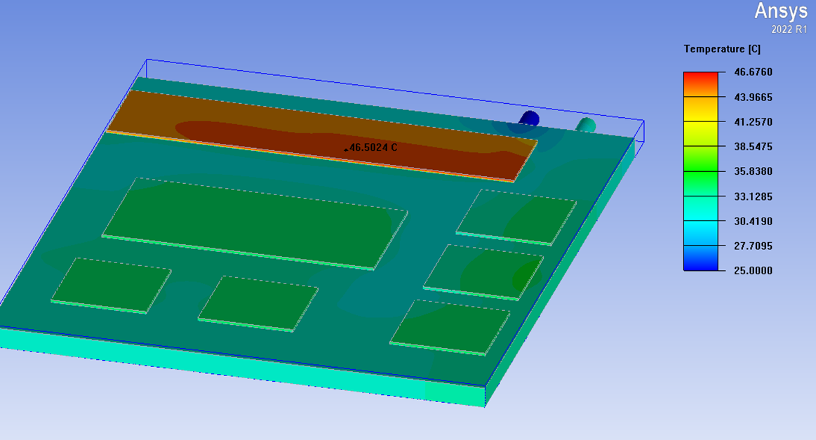
Under normal circumstances, if the TIM has qualified performance, the heat from the chip should be efficiently transferred to the water-cooled plate, and the temperature difference between the surfaces of the two should be controlled within 3-5℃ (only a small interface thermal resistance exists). However, the analysis results of this case show a “reverse temperature difference”:
•Chip surface temperature: 46.5℃ (close to the upper limit of the long-term operating temperature of some chips, which may easily lead to performance degradation during long-term operation)
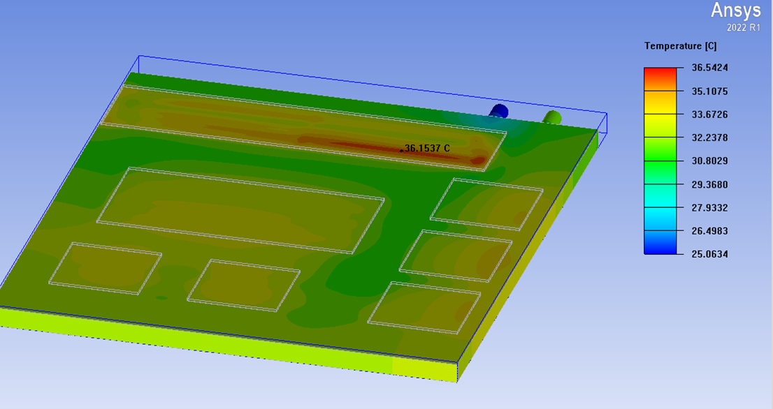
•cold plate surface temperature: 36.5℃ (much lower than the chip temperature, indicating that the heat dissipation capacity of the water-cooled plate itself is not fully utilized and is in an “idle” state)
2.3 Root Cause of the Problem: Low Thermal Conductivity Material Forms a “Thermal Resistance Wall”
The 10℃ temperature difference between the two is mainly due to the “holdback” of the selected TIM:
The pad with a thickness of 0.5mm and a thermal conductivity of 3.0W/(m·K) has high “material thermal resistance”. When heat is transferred from the chip to the water-cooled plate, it first needs to overcome the resistance of this pad, resulting in heat failing to “flow” to the water-cooled plate in a timely manner. Meanwhile, the water-cooled plate maintains a low temperature due to its sufficient heat dissipation capacity, eventually forming a contradictory situation where “the chip accumulates heat while the water-cooled plate is idle”.
If this low-performance pad were not used (relying only on the natural fit of the contact surface, which has air gaps but no additional material thermal resistance), or a TIM with higher thermal conductivity (such as ≥8.0W/(m·K)) and thinner thickness (such as a 0.2mm-thick thermal grease or ultra-thin pad) were selected, the temperature difference between the chip and the water-cooled plate would be significantly reduced, and the chip temperature could drop below 40℃, fully meeting the reliability requirements.
3. Core Selection Principles for High-Power Scenarios: Avoiding the “Low Thermal Conductivity Trap” and Focusing on 3 Key Indicators
As can be seen from the above case, in the thermal management of high-power equipment (power >1000W), the selection of TIMs is by no means “randomly choosing one”. Instead, it should focus on the goal of “reducing total thermal resistance” and pay attention to the following 3 key indicators:
3.1 Prioritize “High Thermal Conductivity”
Thermal conductivity is the core factor determining the thermal conductivity of a material, and it should be “as high as possible” in high-power scenarios. It is recommended to prioritize products with a thermal conductivity of ≥5.0W/(m·K). If the chip power exceeds 2000W (as in this case), it is necessary to further increase it to 8.0-12.0W/(m·K) to reduce the thermal resistance of the material itself from the source and avoid becoming a “bottleneck” for heat transfer.
3.2 Control “Material Thickness” – The Thinner, the Better
The thermal resistance of TIMs is proportional to their thickness (the thicker the thickness, the higher the thermal resistance). On the premise of ensuring the fit of the contact surface, thin products (such as thermal grease or ultra-thin pads with a thickness of 0.1-0.3mm) should be selected as much as possible to reduce the “path length” of heat transfer and avoid superimposing thermal resistance due to excessive thickness.
3.3 Balance “Fit” to Avoid “False Contact”
On the basis of high thermal conductivity and thin thickness, it is necessary to ensure that the material can fit the micro-contact surface between the chip and the water-cooled plate. If the material has high hardness and poor flexibility and cannot fill the micro-gaps, air will still remain, forming additional thermal resistance. For high-power scenarios, it is recommended to use flexible thermal gel or highly malleable thermal grease to ensure “full contact without gaps”.
Conclusion
So how to design a liquid coolin plate ? Kenfa Tech can hel you !In the thermal management of high-power equipment, TIMs are a “key variable” rather than a “fixed accessory”. When selected correctly, they can become a “fast lane” for heat transfer; when selected incorrectly, they will turn into a “roadblock”. The case of the 2425W equipment clearly shows that even if the water-cooling system and water-cooled plate process meet the standards, low-performance TIMs will still cause the entire thermal management system to “fail”. In the future, as chip power further breaks through, the performance requirements for TIMs will be higher. Only by accurately grasping the three cores of “high thermal conductivity, thin thickness, and strong fit” can their value in thermal management be truly exerted, ensuring the stability and reliability of high-power equipment.