I Microchannel Liquid Cooling Plate: A Cooling Savior for High-Power-Density Chips: A Complete Analysis from Process to Design
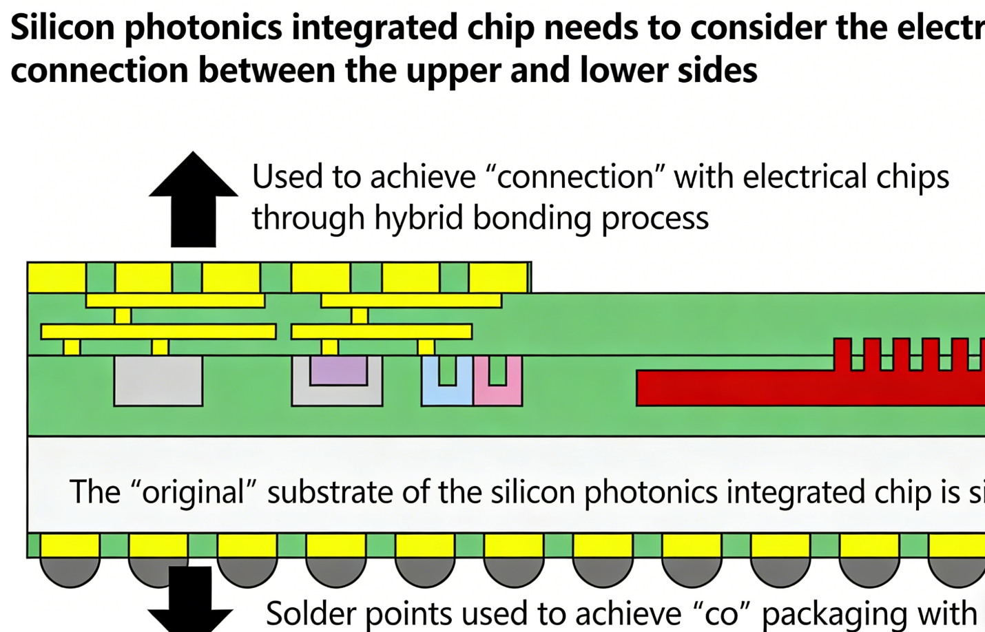
As chip performance continues to break new ground, soaring power density has become an irreversible trend. From AI chips in data centers to IGBT modules in new energy vehicles, local heat flux densities often exceed 100W/cm². Traditional air cooling is no longer able to cope with this “localized high temperature crisis.” Once heat accumulates, the chip will not only experience frequency throttling and lag, but may also be permanently damaged by overheating. This is where microchannel liquid cooling plates, capable of precisely controlling local temperature, come in. By creating tiny flow channels (typically 0.05-0.5mm in diameter) within the plate, these plates allow the coolant to directly contact the heat source, achieving heat dissipation efficiency 5-10 times that of air cooling, making them a core solution for thermal management of high-power chips.
Three core manufacturing processes for producing microchannel liquid cooling plates
1. Profile Extrusion
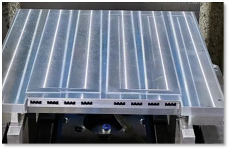
This is the most mature mass-production method. Using a metal extruder, aluminum alloy, copper, and other materials are extruded from a custom mold, forming a liquid cooling plate substrate with microchannels in one step.
• Advantages: High production efficiency, low cost, and smooth channel inner walls (reduced flow resistance). Suitable for applications with large channel sizes (1-3mm) and high-volume production, such as automotive electric drive systems and battery module cooling of thermal management.
• Limitations: Due to the limitations of the extrusion mold, complex and irregular channel shapes cannot be produced. A series connection is required. Long channel lengths can lead to a stable temperature difference between the inlet and outlet. However, this problem can generally be resolved at high flow rates, typically with a temperature difference of around 4-5°C, which is within an acceptable range.
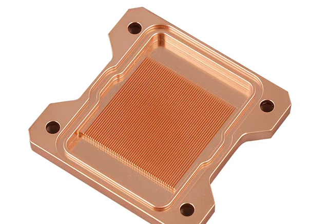
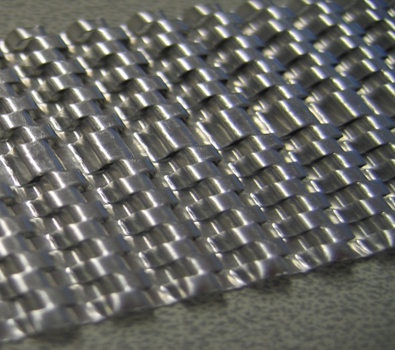
This process, often called a “precision engraver,” uses a high-speed tool to directly cut dense microchannel fins into the surface of a metal substrate (mostly copper or aluminum). The finned cover and base are then welded together via friction stir welding or brazing to form a sealed flow channel. To save costs, the two features can often be locked together using a sealing silicone ring. However, this process carries the risk of leakage and requires strict definition of the silicone ring specifications and sealing grooves.
• Advantages: The flow channel and substrate are seamless, resulting in extremely efficient heat transfer (eliminating interfacial thermal resistance). This allows for the production of extremely thin fins (less than 0.05mm thick) and ultra-fine channels, making it suitable for applications with extremely high heat flux densities, particularly in data centers and large server CPUs/GPUs.
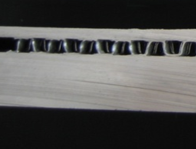
3. Stamping + Brazing process
This is a flexible and innovative approach. A metal sheet (such as stainless steel or aluminum alloy) is first stamped into a grooved flow channel layer, which is then joined to the cover plate via brazing (high-temperature welding) to form a complete liquid cold plate.
• Advantages: High degree of freedom in flow channel design allows for customized, custom-shaped channels based on heat source distribution (such as curved channels that follow the chip contour), and is compatible with a variety of metal materials (including high-temperature stainless steel).
• Limitations: The brazing process requires strict temperature and atmosphere control. A loose weld can easily lead to leakage. The process also involves multiple steps (stamping, cleaning, brazing, and testing), resulting in a long production cycle. Similarly, the irregular stamping pattern creates significant flow channel resistance. Furthermore, due to the brazing filler metal, the finished product requires flow channel cleaning and flow resistance testing. Consequently, this process is relatively costly, with expensive molds and the need for specialized welding fixture materials, such as graphite, which is relatively expensive.
II. “Dual Checks” for Liquid Cold Plate Performance: Testing and Equipment
A completed microchannel liquid cold plate must undergo rigorous testing before it can be deployed. The key focus is on heat dissipation efficiency and flow resistance control, both of which directly impact chip performance and system energy consumption (excessive flow resistance increases pump power consumption).
1. Key Test Items
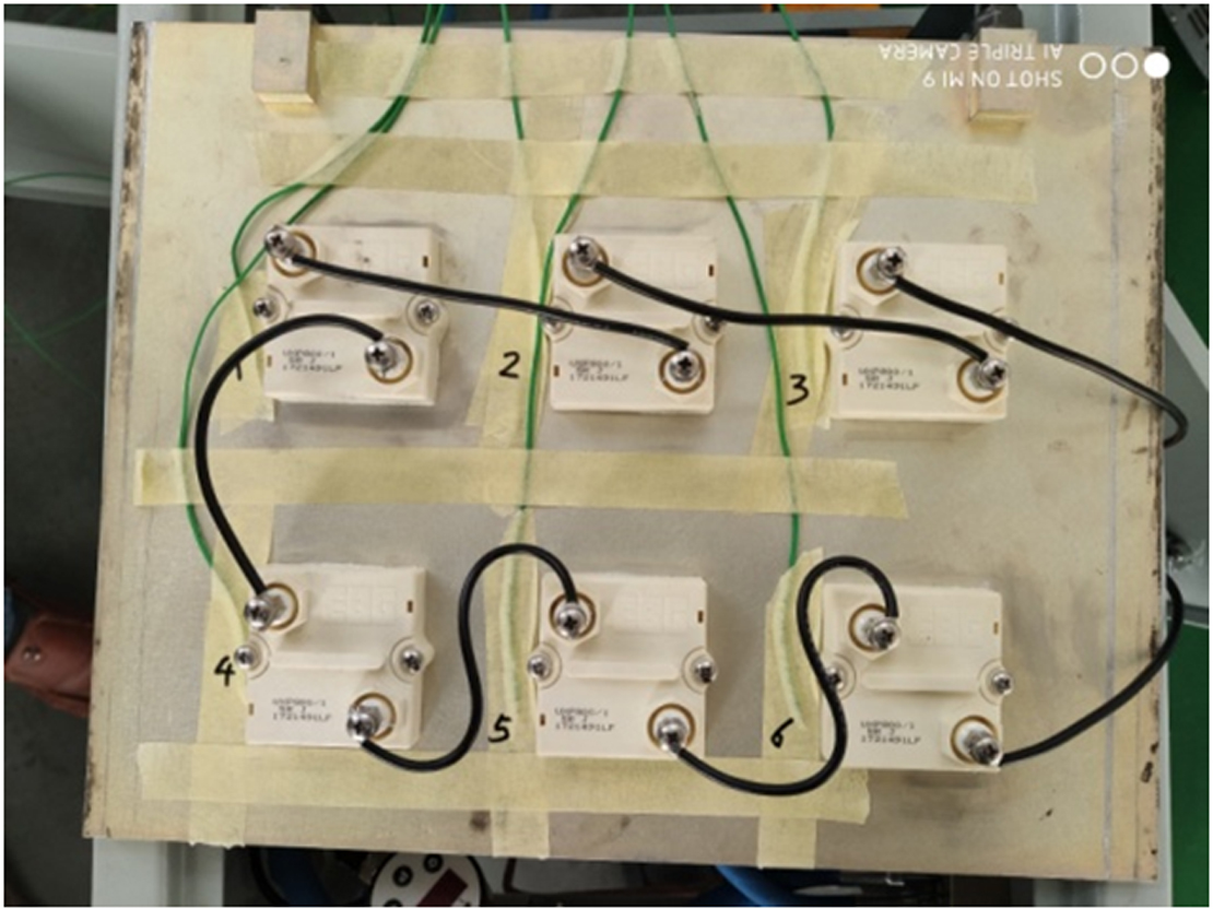
• Heat Dissipation Test: Simulates actual chip operating conditions. A target heat output (e.g., 200W, 500W) is applied via a heater. The surface temperature of the liquid cold plate is monitored using a thermocouple or infrared thermal imager to verify that the “maximum temperature does not exceed XX°C” requirement is met (e.g., server chips typically require a surface temperature ≤85°C).
• Flow Resistance Test: Measure the pressure differential between the inlet and outlet of the liquid cold plate at various flow rates (e.g., 0.5-2m/s) to ensure it is within the system’s allowable range (typically ≤50kPa). This prevents excessive flow resistance from causing poor coolant circulation.
2. Core Tools and Equipment
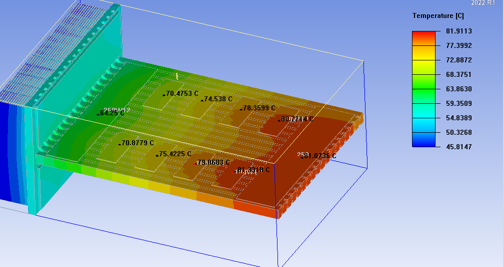
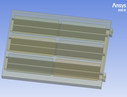
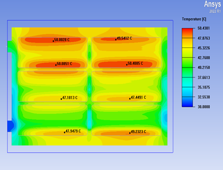
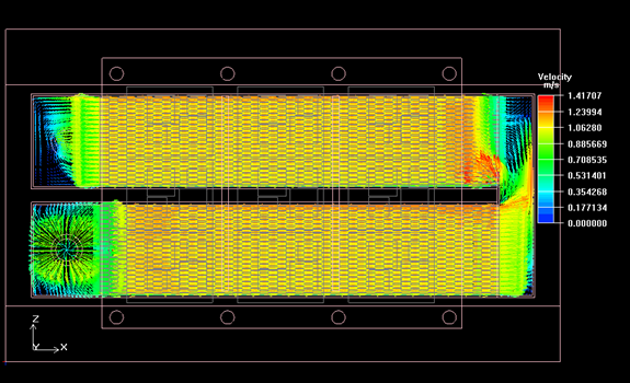
• Simulation Software: ANSYS Icepak, Fluent, and other software are used in the early design phase to simulate coolant flow and temperature distribution, allowing for pre-optimization of the flow channel structure (e.g., adding spoilers and adjusting channel density) to reduce the cost of physical prototype iterations.
• Experimental Equipment: This includes a constant-temperature water tank (to control coolant temperature), a high-precision flow meter (to monitor flow rate), a differential pressure sensor (to measure flow resistance), and a heat flow meter (to calibrate thermal power). Some scenarios also require a high-temperature chamber (to simulate extreme temperatures ranging from -40°C to 85°C).
• Production Equipment: Extruder (for profile processing), high-precision CNC cutting machine (Skived Fin), and stamping press with a vacuum brazing furnace (for stamping and brazing). The brazing furnace requires controlled vacuum or a protective atmosphere (e.g., nitrogen) to prevent metal oxidation.
III. Microchannel Liquid Cold Plate Design: 8 Key Parameters Determine Success
Designing a liquid cold plate isn’t just a matter of “randomly drawing channels”; it requires reverse engineering based on actual operating conditions. The following eight parameters are the cornerstones of design, and none of them can be ignored:
1. Coolant Type: Select the medium based on the environment. Deionized water (low cost and high specific heat capacity) is used for general applications; ethylene glycol-water solutions (anti-icing) are used for low-temperature applications; and mineral oil (insulating and suitable for live components) is used for high-temperature or special environments.
2. Coolant Flow Rate: The higher the flow rate, the better the heat dissipation, but also the greater the flow resistance. A balanced approach is required (typically 0.8-1.5 m/s, depending on the system pump capacity).
3. Coolant Inlet Temperature: This determines the heat dissipation temperature differential. For example, data centers typically require an inlet water temperature ≤35°C, while automotive applications may require ≤45°C.
4. Maximum Allowable Pressure Differential: This is determined by the system pump head. During design, ensure that the pressure differential of the liquid cold plate at the target flow rate is ≤ the pump’s maximum output pressure differential (e.g., ≤30 kPa).
5. Ambient temperature: This affects heat dissipation efficiency. For example, outdoor equipment must consider summer temperatures (above 40°C), while data centers should maintain a temperature around 23°C.
6. Target heat output: Define the total heat dissipation required (e.g., 300W for a single chip, 800W for a multi-chip module) to calculate the total heat dissipation area of the flow channel.
7. Form factor and interface: The liquid cold plate’s dimensions must fit the equipment installation space (e.g., server PCIe card size restrictions). The inlet and outlet connectors should be positioned to facilitate piping layout (side inlet, side outlet, top inlet, top outlet are common). The interface specifications must match the system piping (e.g., quick-connect, threaded).
8. Surface temperature requirement: This is a core specification—the maximum temperature (e.g., ≤80°C) and minimum temperature (to avoid condensation, typically ≥ ambient dew point + 5°C) of the liquid cold plate’s contact surface with the chip must be clearly defined. This directly determines the flow channel density and coolant flow rate.
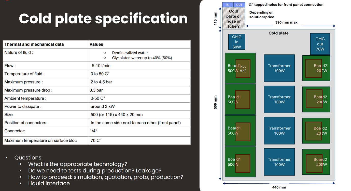
The following chart is the basic parameters and contents that we usually need when conducting thermal design and analysis for our clients. This enables us to clearly understand the client’s requirements and our engineers’ designs.
Conclusion
The value of microchannel liquid cooling plates lies in their ability to address the ‘local thermal anxiety’ of high-power chips through precise manufacturing and design. From the cost-effectiveness of mass production profiles, to the extreme heat dissipation of the Skived Fin, to the flexible customization of stamping and brazing, these three processes address the needs of diverse scenarios. Refined testing and design ensure the stable and efficient operation of the liquid cooling plates. As chip power density continues to increase, microchannel technology will evolve towards even smaller channels (e.g., below 0.1mm) and multi-material composites (e.g., copper-aluminum combinations for cost reduction), continuously safeguarding the cool operation of chips.