Have you ever wondered what makes an electric car accelerate so smoothly? Or how a solar panel efficiently converts sunlight into electricity for your home? Behind these modern marvels, there is a powerful and often overlooked component working silently: the Insulated Gate Bipolar Transistor, or IGBT. This tiny semiconductor is the workhorse of modern power electronics. It evolved by combining the best features of older technologies, giving it a unique ability to handle high power with incredible efficiency.
The main applications of an IGBT are found in high-power electronic systems that require efficient switching. IGBTs are primarily used in variable frequency drives (VFDs) for motor control, inverters for electric vehicles (EVs) and renewable energy systems like solar and wind, and uninterruptible power supplies (UPS). They are also essential in welding equipment, induction heating, and high-speed rail, where controlling large amounts of electrical power efficiently and reliably is critical.
Think of the IGBT as a super-fast, heavy-duty light switch. It can turn massive amounts of power on and off thousands of times per second, which is essential for controlling everything from the speed of a factory motor to the power flow from a battery pack. This guide will provide a deep dive into the world of IGBTs. We will explore what they are, how they work, their key applications, and what the future holds for this foundational technology.
Understanding IGBT: Definition and Fundamentals
An IGBT, or Insulated Gate Bipolar Transistor, is a powerful semiconductor that acts as a high-speed switch. It cleverly combines the easy-to-control gate of a MOSFET with the high-current, low-loss capability of a Bipolar Junction Transistor (BJT). This hybrid design allows it to efficiently manage large amounts of power. This makes it a fundamental building block in modern electronics, from electric cars to solar inverters, where both high performance and efficiency are essential.
What is IGBT?
An IGBT is a true hybrid device that gets the best of both worlds from its parents. Think of it this way:
- The MOSFET Input: The “gate” of the IGBT behaves like a MOSFET. This means it requires very little power to turn on and off. A small voltage applied to the gate is all it takes to control the entire device.
- The BJT Output: The main body of the IGBT acts like a BJT. This allows it to handle very high currents with minimal power loss (low on-state voltage), which is crucial for efficiency in high-power applications.
By combining these features, the IGBT gives engineers a component that is both easy to control and incredibly powerful.

Construction and Structure of IGBT
The IGBT is built from multiple layers of semiconductor material. While the details are complex, its basic structure can be understood by looking at its four alternating layers. From bottom to top, these layers are typically:
- P+ Collector: This bottom layer serves as the collector terminal and is where the current exits.
- N- Drift Region: This is a thick, lightly doped layer that is designed to block high voltages when the IGBT is turned off.
- P Body Region: This layer is critical for the device’s switching action. The control gate sits above it.
- N+ Emitter: This top layer serves as the emitter terminal and is where the current enters the device.
An insulated gate terminal, made of a layer of silicon dioxide, is located over the P Body region. This gate is what provides the easy, low-power control.
Working Principle of IGBT
The magic of the IGBT happens when you apply a voltage to its gate. When a positive voltage is applied, it creates a conductive channel in the P Body region beneath it. This channel allows electrons to flow from the N+ Emitter into the N- Drift Region. This initial flow of electrons acts as the trigger for the main BJT part of the device, turning it on and allowing a much larger current to flow from the collector to the emitter with very low resistance. To turn the device off, you simply remove the voltage from the gate. The channel disappears, the current stops flowing, and the device can once again block a high voltage.
Think of the gate as a key. A small turn (applying voltage) unlocks a massive floodgate (the BJT structure), allowing a huge amount of current to rush through. When you remove the key, the floodgate slams shut, stopping the flow instantly.
Equivalent Circuit Model
For circuit designers, thinking about the complex physics inside the IGBT isn’t always practical. Instead, they often use a simplified “equivalent circuit model.” This model represents the IGBT as a combination of a MOSFET and a BJT. It shows the MOSFET controlling the base of the BJT, which accurately reflects how the device behaves. This simplified model is incredibly useful for analyzing and simulating circuits, allowing engineers to predict how the IGBT will perform without needing to be semiconductor physicists.
Types of IGBT
Just like you wouldn’t use the same type of tire for a race car and a tractor, not all IGBTs are created equal. Engineers have developed different types of IGBTs, each optimized for specific jobs. These variations are based on the internal structure of the semiconductor. The main types include Punch-Through (PT) and Non-Punch-Through (NPT) designs, along with newer, more advanced variants that push the boundaries of performance and efficiency even further.
Punch-Through (PT) IGBT
Punch-Through IGBTs are the speed demons of the family. They have what is called an “asymmetrical” structure, which includes an extra N+ buffer layer. This special layer helps to quickly remove charge carriers when the device is turned off. The result?
- Faster Switching Speed: PT IGBTs can turn on and off more rapidly than their NPT counterparts.
- Lower On-State Voltage Loss: They are slightly more efficient when turned on.
This high-speed capability makes them ideal for applications that operate at high frequencies, such as switch-mode power supplies (SMPS) and some types of inverters.
Non-Punch-Through (NPT) IGBT
Non-Punch-Through IGBTs are the rugged workhorses. They have a simpler, “symmetrical” structure without the extra buffer layer. While this makes them a bit slower, it gives them some very important advantages:
- Greater Robustness: NPT IGBTs are tougher and can handle short-circuit conditions better.
- Better Thermal Stability: Their performance is more consistent across a wide range of temperatures.
- Easier to Parallel: It is simpler to connect multiple NPT IGBTs together to handle even larger currents.
These features make them the preferred choice for tough, high-power applications like industrial motor drives and electric vehicle inverters, where reliability is absolutely critical.
Other Variants: Trench-Gate, Field-Stop, and Reverse-Conducting IGBTs
The world of IGBTs is always evolving. Engineers are constantly finding clever ways to improve their design, leading to a new generation of devices that are smaller, faster, and more efficient than ever before.
Some of these exciting new variants include:
- Trench-Gate IGBTs: These devices change the gate from a flat surface to a vertical trench dug into the silicon. This increases the channel density, which significantly lowers the on-state voltage loss and improves overall efficiency.
- Field-Stop (FS) IGBTs: This is a newer design that combines the best of both PT and NPT types. It has the fast switching of a PT device but with the low losses and robustness of an NPT device.
- Reverse-Conducting (RC) IGBTs: These clever devices integrate a freewheeling diode directly into the same piece of silicon as the IGBT. This saves space, reduces manufacturing costs, and improves thermal performance in applications like motor drives.
Characteristics, Advantages, and Disadvantages of IGBT
To truly understand where IGBTs shine, you need to look at their strengths and weaknesses. Like any technology, they involve trade-offs. The IGBT’s unique design gives it a powerful set of advantages, but it also comes with limitations. Choosing the right component means knowing when these trade-offs work in your favor. This balance is what makes an IGBT perfect for some jobs and less suitable for others.
Key Advantages
The hybrid nature of the IGBT is its greatest strength. It delivers a combination of features that are hard to find in any other single component:
- High Power Capability: IGBTs can handle very high voltages (over 1000V) and large currents (hundreds of amps) at the same time.
- Low On-State Loss: When the IGBT is switched on, it has a very low voltage drop across it. This means less power is wasted as heat, leading to higher overall efficiency.
- Simple Gate Drive: Because its gate is like a MOSFET, it takes very little energy to switch an IGBT on or off. This makes the control circuits much simpler and cheaper to design.
Disadvantages and Limitations
However, the IGBT is not perfect. Its BJT-like structure introduces a few drawbacks:
- Slower Switching Speed: Compared to a MOSFET, an IGBT switches more slowly. This limits its use in very high-frequency applications (typically above 20-50 kHz).
- Tail Current: When an IGBT is turned off, a small amount of current continues to flow for a brief moment. This “tail current” creates extra heat and power loss.
- Thermal Considerations: Handling high power always generates heat. Because of their power density, IGBTs produce a significant amount of waste heat that must be managed. Without an effective cooling solution, this heat can damage the device and reduce its lifespan.
In power electronics, there is always a trade-off. The IGBT sacrifices some of the raw speed of a MOSFET to gain the incredible power-handling and low losses of a BJT.
Comparison with BJT and MOSFET
Choosing the right transistor often comes down to a direct comparison. Here is a simple table to show where the IGBT fits in:
| Feature | BJT | MOSFET | IGBT |
|---|---|---|---|
| Control | Current-controlled | Voltage-controlled | Voltage-controlled |
| Switching Speed | Slow | Very Fast | Medium |
| Voltage Rating | High | Medium | Very High |
| Current Rating | High | Medium | Very High |
| On-State Loss | Low | Higher (at high voltage) | Very Low |
| Best For | Low-frequency power | High-frequency, low voltage | High-power, medium frequency |
Key Applications of IGBT
The IGBT’s unique blend of high power and easy control has made it an essential component across dozens of industries. This is where theory meets reality. From the factory floor to the open road, IGBTs are the engine behind our modern, electrified world. They perform the critical task of power conversion—changing electricity from one form to another—with incredible efficiency. Let’s explore some of the most important places you’ll find these powerful switches at work.
IGBT in Motor Drives and Variable Frequency Drives (VFDs)
This is perhaps the most common application for IGBTs. Most large electric motors used in industrial settings are AC motors, which are designed to run at a fixed speed. A Variable Frequency Drive (VFD) uses a group of IGBTs to convert fixed AC power from the grid into variable DC, and then back into AC at any frequency. This allows for precise control over the motor’s speed and torque.
Why is this so important? By matching a motor’s speed exactly to the needs of the application (like a pump or a fan), VFDs can reduce energy consumption by as much as 50%. In a large factory, this translates to massive cost savings and a much smaller carbon footprint. IGBTs are the heart of these drives, switching thousands of times per second to create the perfect AC waveform to run the motor efficiently.
Applications in Renewable Energy Systems
Renewable energy sources like solar panels and wind turbines produce direct current (DC) power. However, our homes, businesses, and power grids all run on alternating current (AC). The device that bridges this gap is called an inverter, and modern, high-efficiency inverters are built around IGBTs.
In a solar energy system, IGBTs in the inverter chop up the DC electricity from the panels and reshape it into a clean AC sine wave that matches the grid. In massive wind turbines, they manage the variable power generated by the blades and convert it into a stable form of electricity. The high power-handling and efficiency of IGBTs are critical here, as every watt of power lost in the conversion process is a watt of clean energy wasted.
IGBT in Electric Vehicles (EVs) and Hybrid Vehicles
When you press the accelerator in an electric car, you are directly controlling a set of powerful IGBTs. The instant, silent torque that EVs are famous for is a direct result of the IGBT’s ability to precisely manage the flow of power from the battery to the motor.
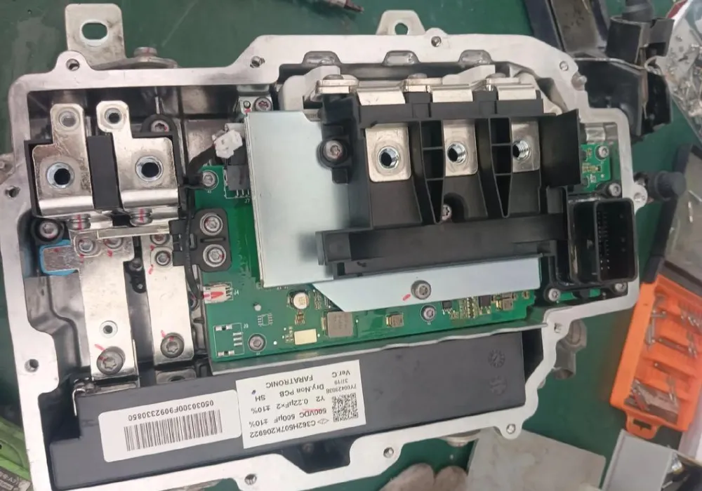
IGBTs are the star players in an EV’s powertrain. The main component, called the traction inverter, uses IGBTs to convert DC power from the high-voltage battery pack into the AC power needed to drive the electric motor. Their ability to handle hundreds of kilowatts of power while remaining efficient is key to maximizing the vehicle’s range and performance. IGBTs are also used in:
- On-Board Chargers (OBC): For converting AC power from your home outlet into DC to charge the battery.
- DC Fast Charging Stations: Where very high-power IGBTs manage the rapid flow of electricity directly into the battery.
Uninterruptible Power Supplies (UPS) and Power Conditioning
For critical facilities like hospitals, data centers, and financial institutions, a power outage is not an option. An Uninterruptible Power Supply (UPS) provides instant backup power. When the main power fails, the UPS inverter, powered by IGBTs, immediately kicks in. It converts DC power from a battery bank into clean, stable AC power to keep the critical systems running without interruption. IGBTs are chosen for this role because of their reliability and their ability to produce a perfect sine wave, which is essential for sensitive electronic equipment.
Rail and Transportation Systems
The powerful electric motors that drive modern trains, trams, and subways are controlled by high-power IGBT modules. These traction drives handle enormous amounts of electricity—often at thousands of volts. IGBTs provide the robust and reliable switching needed to control the speed and braking of these heavy vehicles smoothly and efficiently. Their ruggedness and ability to operate in harsh environments make them perfect for the demands of the transportation industry.
Induction Heating and Welding Equipment
Have you ever seen an induction cooktop heat a pan without any flame? That technology is powered by IGBTs. Induction heating and welding work by using a high-frequency alternating magnetic field to generate heat directly within a metal object. To create this field, IGBTs are used to switch a large current on and off at very high frequencies (typically 20-100 kHz). This precise, high-speed switching allows for incredibly fast and controlled heating, making it popular in both consumer kitchens and industrial manufacturing.
Smart Grid and HVDC Transmission
Moving electricity over long distances is more efficient using high-voltage direct current (HVDC). At each end of an HVDC line, massive converter stations are needed to change the power between AC and DC. These stations use large arrays of very high-voltage IGBTs to handle the power conversion for entire cities or regions. IGBTs are also playing a growing role in the “smart grid,” where they are used in devices that help stabilize the grid and manage the flow of renewable energy.
Other Emerging Applications
The versatility of IGBTs means they are constantly finding their way into new and exciting fields. Some of these include:
- Medical Devices: Powering the strong magnetic fields in MRI machines and other advanced imaging equipment.
- Aerospace: Used in aircraft power conversion systems and flight control actuators.
- Consumer Electronics: Found in high-end appliances like induction cooktops and energy-efficient air conditioners.
Implementation Considerations and Circuit Examples
Using an IGBT is more than just plugging it into a circuit. To unlock its full potential, engineers must carefully design the systems around it. This involves providing the right signals to control it, protecting it from damage, and, most importantly, managing the heat it produces. Getting these details right is the difference between a reliable, efficient product and one that fails prematurely. Let’s look at the key considerations for successfully implementing IGBTs.
IGBT Circuit Design Basics
A well-designed circuit is essential for an IGBT to perform reliably. There are three key elements to get right:
- Gate Drive Requirements: The gate driver is a small circuit that acts as the “translator” between the low-power control signals from a microprocessor and the IGBT’s gate. It must provide a clean, stable voltage (typically +15V to turn on, 0V or a negative voltage to turn off) with enough current to switch the IGBT quickly.
- Snubber Circuits: When an IGBT switches off a large current, it can cause a sudden voltage spike. A snubber circuit, usually a simple network of resistors and capacitors, is placed near the IGBT to absorb this spike and protect the device from damage.
- Protection Strategies: High-power circuits need multiple layers of protection. This includes features to detect over-current conditions (like a short circuit) and over-temperature situations, which can shut the IGBT down safely before it is destroyed.
Common IGBT Application Circuits
While specific circuit diagrams can be very complex, most IGBT applications are based on a few common building blocks, or “topologies.” For example, many inverters for motor drives and solar applications use an H-Bridge topology. This setup uses four IGBTs to switch power in a way that can create a positive or negative voltage, which is the basis for building an AC sine wave from a DC source. Similarly, UPS systems often use specialized inverter circuits designed for maximum reliability and clean power output.
Challenges in IGBT Implementation
Even with a perfect circuit design, engineers face practical challenges when building real-world systems. Three of the biggest hurdles are:
- Heat Dissipation: This is the number one challenge. Every watt of power an IGBT wastes becomes heat. In a high-power system, this can be hundreds or even thousands of watts concentrated in a very small area. This heat must be removed effectively.
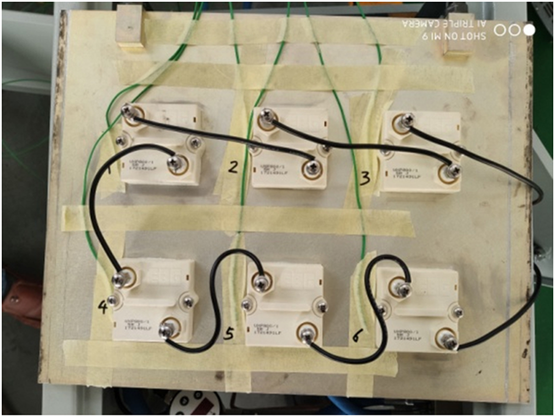
- Paralleling Devices: For very high-current applications, a single IGBT may not be enough. Engineers often connect multiple IGBTs in parallel. However, this must be done carefully to ensure they share the current evenly.
- Reliability Testing: High-power systems must be incredibly reliable. This requires rigorous testing under extreme conditions to ensure the IGBTs and the surrounding circuit can withstand the stresses of real-world operation.
Of all the challenges, managing heat is the most critical. An IGBT that runs too hot will have a drastically shorter lifespan and can fail unexpectedly. A robust thermal management solution is not just an accessory; it is a core part of the system design.
Future Trends and Innovations in IGBT Technology
The world of IGBTs is not standing still. As the demand for more efficient power electronics grows, researchers and engineers are pushing the limits of what these devices can do. The future of IGBTs is focused on making them smaller, faster, tougher, and smarter. These advancements are crucial for supporting the global transition to sustainable energy and more advanced electronics.
Innovation in IGBT technology is directly tied to our progress in electric vehicles, renewable energy, and smart grids. Better IGBTs mean more efficient and reliable green technology for everyone.
Here are some of the key trends shaping the future:
- Advanced Materials: While silicon is the traditional material for IGBTs, new “wide-bandgap” materials like Silicon Carbide (SiC) are emerging. Hybrid SiC-IGBTs can switch faster, handle higher temperatures, and have lower losses, leading to even more efficient systems.
- Higher Voltage Ratings: There is a constant push to develop IGBTs that can handle even higher voltages (up to 10,000V and beyond). This is critical for next-generation HVDC power grids and heavy-duty electric transportation.
- Smarter Integration: Future IGBT modules will be more intelligent. They will include integrated sensors that monitor temperature and current in real-time. This data can be used with AI algorithms for predictive maintenance, allowing systems to flag a potential failure before it happens.
Frequently Asked Questions (FAQs)
What is IGBT used for?
An IGBT is used as a high-power, high-efficiency electronic switch. Its main job is to control the flow of large amounts of electricity in applications like electric vehicle inverters, industrial motor drives, solar and wind energy systems, and uninterruptible power supplies (UPS).
What are the main applications of IGBT in power electronics?
In power electronics, IGBTs are primarily used for power conversion. This includes converting DC to AC in inverters (for EVs and solar), controlling motor speed in variable frequency drives (VFDs), and enabling high-frequency switching in welding and induction heating equipment.
What is the difference between IGBT and MOSFET?
The main difference is their ideal application range. A MOSFET is extremely fast and best for high-frequency, lower-voltage applications. An IGBT is slower but can handle much higher voltages and currents with lower power loss, making it ideal for high-power, medium-frequency applications.
What are the advantages and disadvantages of IGBT?
The main advantages are high power-handling capability, very low on-state power loss (high efficiency), and simple, low-power gate control. The main disadvantages are slower switching speed compared to MOSFETs and the significant amount of waste heat they generate, which requires careful thermal management.
How is IGBT applied in electric vehicles?
In EVs, IGBTs are the core component of the traction inverter. This device takes DC power from the battery and, using IGBTs to switch it at high speed, converts it into the AC power needed to run the electric motor, controlling the car’s speed and torque.
What is the working principle of IGBT in inverters?
In an inverter, IGBTs work in pairs to rapidly switch DC voltage on and off. By carefully controlling the timing and duration of this switching—a technique called Pulse Width Modulation (PWM)—they can construct a sine wave, effectively creating AC power from a DC source.
Conclusion: Powering the Future, One Switch at a Time
The Insulated Gate Bipolar Transistor is more than just another component; it is a fundamental enabler of our modern, electrified world. From making electric vehicles practical to helping us harness renewable energy, the IGBT’s unique ability to efficiently control high power is everywhere. Its combination of a MOSFET’s easy control and a BJT’s raw power has made it an indispensable tool for engineers across countless industries. As technology continues to demand more power in smaller spaces, the role of the IGBT will only become more critical.
However, unlocking the full potential of an IGBT-based system requires more than just choosing the right device. As we’ve seen, managing the immense heat these components generate is the single most important factor for ensuring reliability, efficiency, and a long service life. A powerful IGBT without proper cooling is a system destined to fail.
This is where a holistic approach to design becomes essential. Your thermal management solution is not an afterthought—it is a core part of your product’s success. Don’t let heat become your bottleneck.
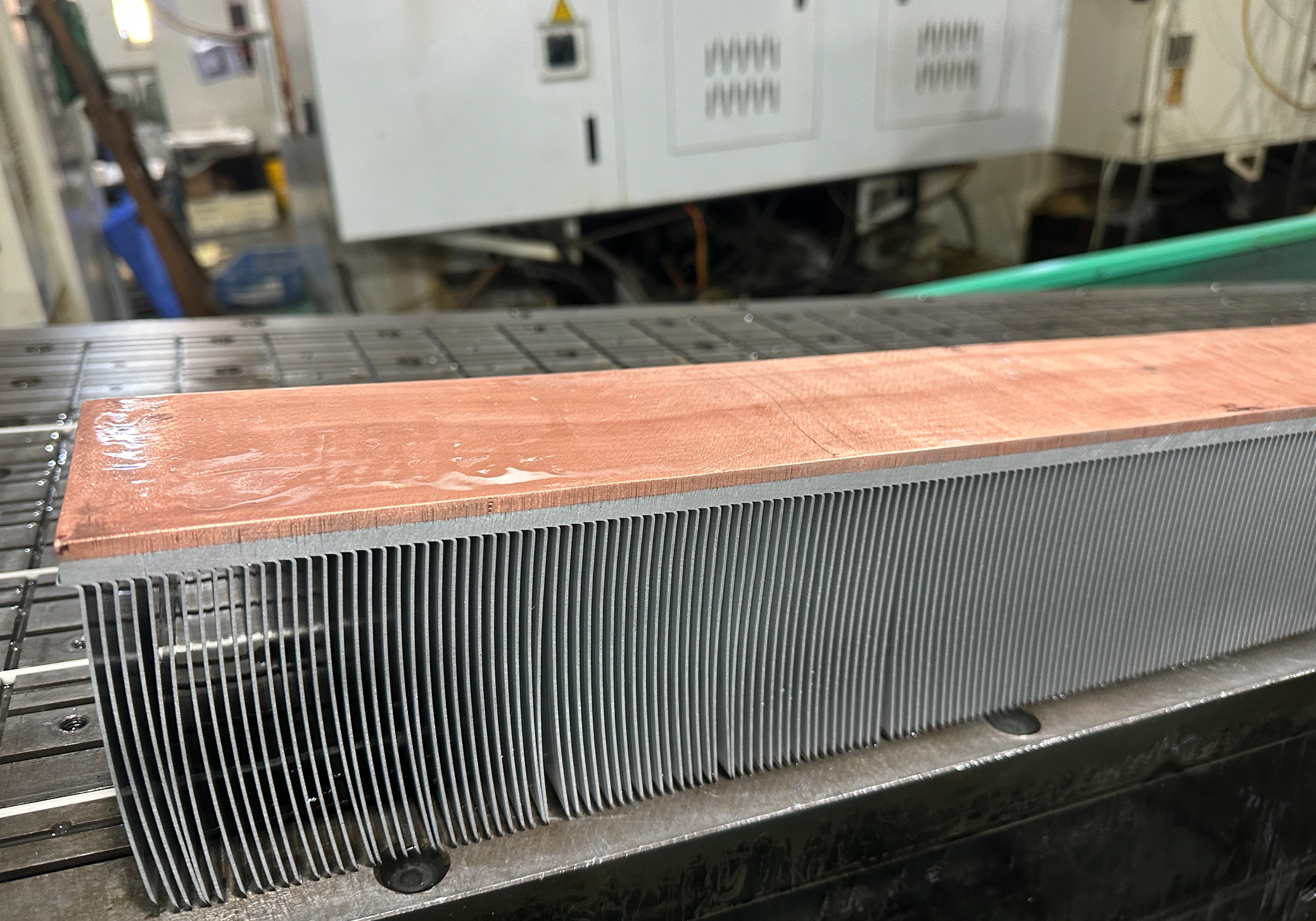
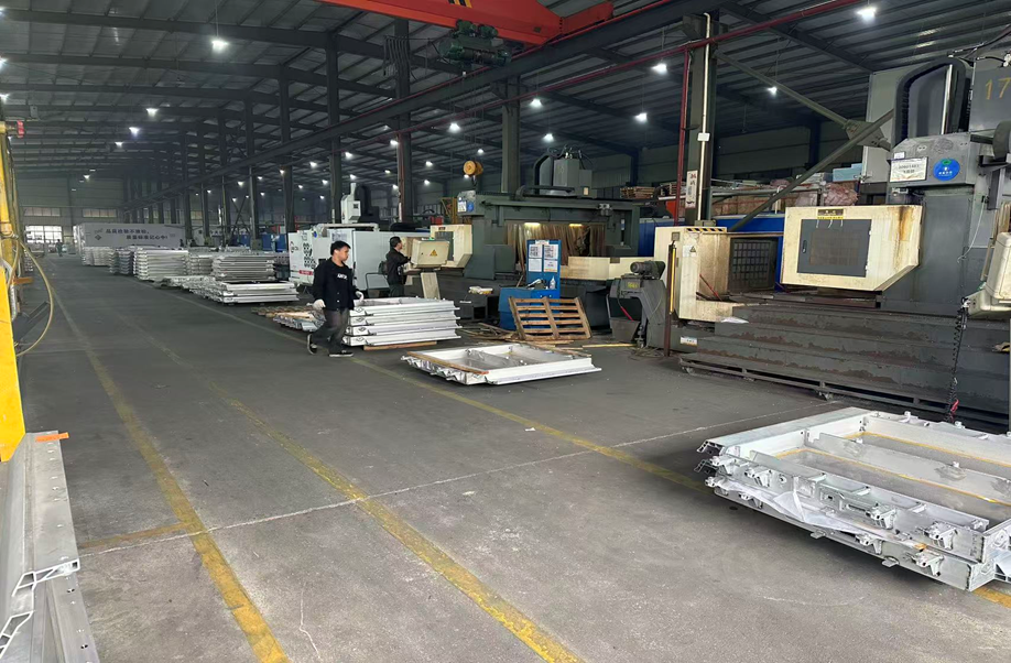
At KenfaTech, we specialize in creating custom, high-performance thermal solutions that are engineered to meet the demanding needs of modern power electronics. Whether your application requires an advanced liquid cold plate for an EV inverter or a precision-machined heat sink for an industrial drive, our team has the expertise to design and manufacture a solution that keeps your IGBTs running cool and reliably.
Ready to build a more efficient and reliable high-power system? Contact the experts at KenfaTech today to discuss your project and discover how our custom thermal management solutions can help you succeed.


