
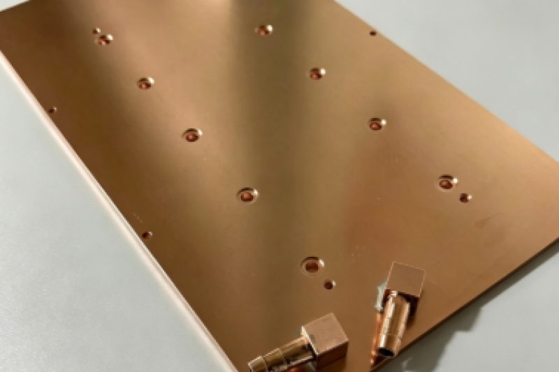
Our engineers conduct an in-depth comparison among copper tube embedded cold plates, vacuum brazed cold plates and friction stir welded copper cold plates. We analyze differences in thermal resistance, temperature uniformity, pressure drop, reliability and cost across multiple dimensions, delivering optimal liquid cooling selection references for electronic thermal management engineers.
Core Keywords:
liquid cold plate, copper tube embedded cooling, vacuum brazed cooling, thermal resistance, channel pressure drop, Friction Stir Welding Process cold plate ,electronic thermal management.
Long-tail Keywords:
high heat flux cooling, uniform temperature cooling, industrial liquid cooling, server thermal solution, power device heat dissipation
1. Introduction
With the continuous iteration of high-power electronic equipment including AI computing servers, industrial lasers and new energy converters, the heat flux density of core heat sources has surged from the traditional 25–80 W/cm² to 150–250 W/cm². Liquid cold plates have fully replaced air cooling and become the core mainstream thermal management carrier for high-load equipment.
Within the industrial liquid cooling sector, copper tube embedded cold plates, as well as vacuum-brazed microchannel cold plates (aluminum or copper versions), represent the two most mature and mass-producible mainstream manufacturing processes. Most existing public resources only list superficial parameter gaps, lacking in-depth breakdowns of the fundamental differences in heat transfer mechanisms and applicable working condition boundaries between the two types of cold plates.
Based on hands-on manufacturing experience and finite element simulation verification, this paper delivers an original comprehensive comparative analysis across six dimensions: structural manufacturing processes, heat transfer paths, core thermal performance, fluid characteristics, long-term reliability and mass production costs. It addresses the core pain point of engineering scheme selection: which process delivers superior heat dissipation efficiency and overall cost-performance under varying heat source layouts and operating conditions.
2. Fundamental Differences in Structure and Heat Transfer Mechanism
The performance gap between the two types of cold plates does not stem from superficial material differences, but from fundamental disparities in forming processes and heat transfer paths. This chapter thoroughly analyzes the core mechanisms that determine their maximum heat dissipation capacity.
2.1 Copper Tube Embedded Cold Plate:
Composite Structure with Dual Heat-Conducting Media The copper tube embedded cold plate adopts a composite assembly structure composed of a 6061 aluminum substrate and seamless oxygen-free copper tubes, which is a non-metallurgical forming process. The workflow includes CNC grooving on aluminum plates, bending and shaping copper tubes, hydraulic tube expansion for tight fitting, and filling gaps with high-thermal-conductivity media for curing.
Its heat transfer path features typical layered characteristics: Heat source → thermal interface pad → lateral heat spreading of aluminum substrate → interfacial filling layer → copper tube wall → cooling liquid.
This structure brings two-sided performance traits. On the positive side, oxygen-free copper tubes feature an axial thermal conductivity of 385 W/(m·K), more than twice that of aluminum. They can rapidly conduct and disperse concentrated local hot spots to curb localized temperature rise. On the negative side, the assembled structure inevitably generates interfacial contact thermal resistance. When coolant flows inside the smooth tube wall, a laminar boundary layer forms between the coolant and copper wall. Higher flow velocity creates a thicker laminar layer that severely hinders heat penetration, drastically degrading heat conduction performance. Accordingly, interfacial contact thermal resistance and laminar layer formation act as the core bottlenecks limiting overall heat exchange efficiency.
2.2 Vacuum Brazed Cold Plate: Integrated Metallurgical Microchannel Structure
Vacuum brazed cold plates are monolithic homogeneous structures made entirely of aluminum or pure copper, fabricated via full-plate vacuum brazing. The manufacturing process: microchannels and turbulence fins are pre-machined on upper and lower aluminum plates, which are then welded at high temperature in a vacuum with aluminum-silicon brazing foil. The base plate and flow channels are metallurgically bonded without assembly gaps. Another option is the friction stir welding (FSW) process for copper plates: CNC machining is performed first to fabricate grooved microchannels with non-smooth inner channel walls. This design enables turbulent flow of coolant inside for highly efficient heat dissipation. Its heat transfer path is extremely short and efficient: Heat source → thin aluminum plate wall → cooling liquid. Without multi-layer medium interfaces, the total thermal resistance only consists of solid wall thermal resistance and liquid convection thermal resistance, resulting in minimal heat conduction loss. Its core advantage lies in ultra-high heat exchange area density. The built-in microchannels and fins generate turbulent flow, drastically expanding the solid-liquid contact area. This allows massive heat to transfer into the coolant and be carried away rapidly.
3. Quantitative Comparison of Core Thermal Performance (Standard Working Conditions)
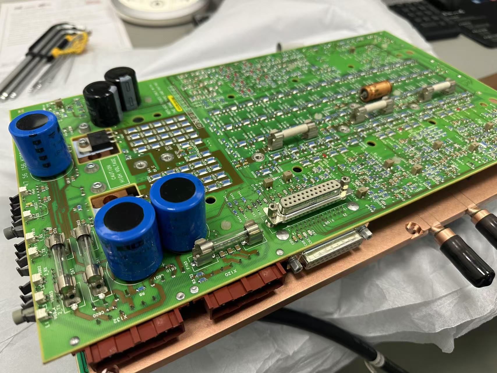
The comparison is carried out based on the liquid cold plate for a Siemens RF device, with the cold plate dimensions of 382 × 222 × 8 mm, inlet water temperature of 25°C, circulating flow rate of 4 L/min, and ambient temperature of 25°C. Relying on customer test data and simulation results, this chapter quantifies the performance gap between the two types of cold plates.
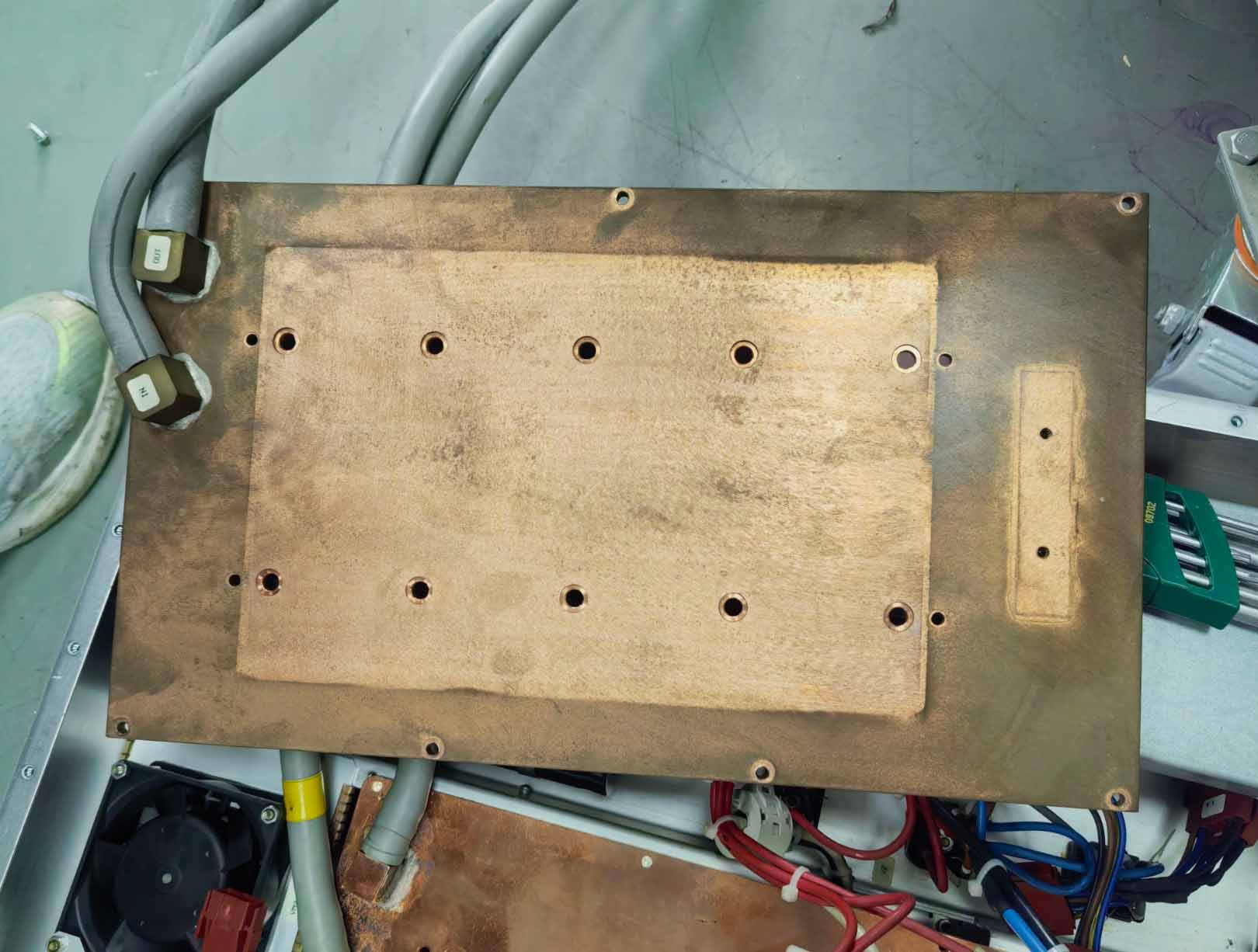
3.1 Total Thermal Resistance and Hot Spot Suppression Capacity
Thermal resistance serves as the core metric for evaluating the heat dissipation efficiency of cold plates; the lower the thermal resistance, the stronger the heat transfer capacity.Copper tube embedded cold plates feature a total thermal resistance ranging from 0.035 to 0.06 ℃/W, among which the interfacial contact thermal resistance accounts for 40%–60% of the total value. Tighter tube expansion bonding delivers lower thermal resistance, while aging of filling media will trigger a sharp rise in thermal resistance. Its core merit lies in hot spot suppression. Under local high heat flux conditions of 50–70 W/cm², concentrated heat is quickly conducted away by copper’s superior thermal conductivity, yet its local peak temperature is 8.2–12.3℃ higher than vacuum brazed cold plates. This will raise the temperature of RF chips and force the chips to operate at reduced frequencies.
For vacuum brazed cold plates, total thermal resistance is steadily maintained at 0.012–0.018 ℃/W, with no interfacial gaps and minimal heat transfer loss. Under uniform surface heat load of 150–200 W/cm², it achieves higher overall heat exchange efficiency, with the average surface temperature 9.5–12.4℃ lower than embedded copper tube cold plates. RF chips maintain stable temperatures without frequency throttling.
3.2 Surface Temperature Uniformity
Temperature uniformity is a critical assessment indicator for high-precision equipment such as AI server GPUs and phased array radars.Heat conduction of copper tube embedded cold plates fully relies on copper tube layout. Areas between tubes feature lengthy heat transfer paths, equivalent to a series structure for multi-chip heat sources. The typical overall surface temperature difference ranges from 5 to 8℃, suitable for working conditions without strict full-area temperature uniformity requirements. Vacuum brazed cold plates adopt full-coverage dense microchannel design. Every area on the plate can exchange heat directly with coolant via parallel flow channels, keeping the overall temperature difference stably within ≤2℃, which fully meets industrial and automotive-grade high-precision temperature uniformity standards.
3.3 Channel Pressure Drop and System Pump Power Consumption
Thermal performance cannot be evaluated separately from system energy consumption, as channel pressure drop directly determines the power load of circulating pumps and total energy consumption of liquid cooling systems.Embedded copper tube cold plates adopt smooth seamless round flow channels with low fluid friction resistance. Under standard flow rate, the pressure drop only ranges from 20 to 35 kPa, resulting in light pump loads, making them ideal for mobile devices and small low-power cooling units. However, excessive bending may cause local extrusion deformation of copper tubes and a dramatic surge in pressure drop.
The microchannels and skived fin turbulence structures of brazed cold plates enhance heat exchange yet drastically increase fluid resistance. Under identical working conditions, the pressure drop reaches 60–120 kPa, requiring high-pressure high-flow circulating pumps and leading to noticeably higher long-term system energy consumption. Even so, its overall efficiency surpasses embedded copper tube cold plates. Thanks to lower operating temperatures, we can reduce pump power and flow velocity while still meeting the heat exchange demands of the entire system.
4. Analysis of Long-Term Reliability and Process Adaptability
Short-term heat dissipation data can only verify instantaneous performance. Long-term reliability and mass production scalability are the core factors that determine the practical engineering value of cold plates.
4.1 Pressure Resistance, Sealing Performance and Aging Resistance
The flow channels of copper tube embedded cold plates are weld-free. To minimize thermal resistance, copper tubes with an original wall thickness of 1.2 mm are adopted. After tight press-fitting, a 0.5 mm layer is removed via CNC machining, leaving an actual tube wall thickness of only 0.7 mm. The copper tube itself carries zero risk of liquid leakage, yet the bonding interface between copper tubes and the aluminum substrate acts as the weak point, with a standard pressure resistance of 1.0–1.6 MPa. After repeated thermal shock cycles, the filling medium tends to develop micro delamination, which causes interfacial thermal resistance to rise year by year and leads to gradual degradation of heat dissipation performance.
Vacuum brazed cold plates feature an integrated metallurgically bonded structure with zero internal gaps, delivering a pressure resistance of 2.5–3 MPa. They can withstand high-pressure pulsation and severe vibration, with no leakage detected after 100,000 pressure cycle tests. Friction stir welding (FSW), in particular, fuses materials into a unified monolithic component through high-temperature plasticization, eliminating leakage risks entirely.
4.2 Production Cycle and Mass Production Cost Analysis
The copper tube embedding process requires low equipment investment and features simple machining workflows. It does not rely on costly vacuum brazing furnaces, offering short single-unit processing cycles and low prototyping costs for small batches. It boasts prominent cost advantages for large-size non-standard cold plates, priced 25%–35% lower than brazed counterparts. This process serves as the optimal solution for R&D prototypes and small-batch custom projects, and it is also a cost-effective option for low-power chips. You may refer to our paper regarding cold plate flow channel selection and design under different power loads.
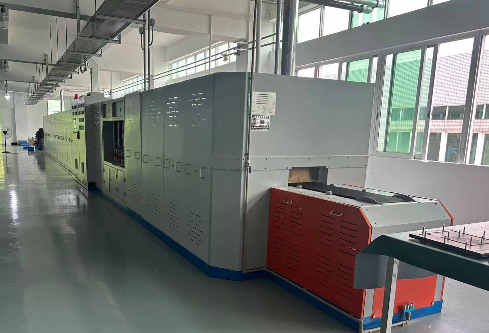
The vacuum brazing process relies on high-temperature vacuum furnaces for batch manufacturing, characterized by long furnace cycles and high energy consumption, which drives up unit costs for small-batch orders. However, unit costs drop sharply under large-scale mass production. This process enables the fabrication of ultra-thin plates of 6–8 mm thickness, making it irreplaceable for lightweight equipment and space-constrained applications. Currently, GPU cold plates for AI hardware and optical module cold plates are manufactured via this process. Friction stir welding is an alternative solution with lower upfront equipment investment; it eliminates the flow channel cleaning step during inspection to further cut costs. In contrast, vacuum brazing leaves brazing residue, which requires an additional high-pressure cleaning procedure.
5. Application Boundaries and Engineering Selection Criteria
Neither of the two processes holds absolute advantages or disadvantages. The core of selection lies in matching heat source characteristics, operating environments and mass production attributes of the project. This chapter defines the precise applicable boundaries for both types of cold plates. You may refer to our previous paper on how to choose flow channel selection and design schemes of cold plates for chips with different power levels.
5.1 Scenarios Where Copper Tube Embedded Cold Plates Are Preferred
• Single-point high heat flux heat sources: industrial fiber lasers, high-power single IGBT modules, medical transmitting equipment (heat flux density ≥15 W/cm²);
• Small-batch custom projects and large-size non-standard cold plate projects with limited engineering budgets;
• Liquid cooling systems with restricted circulating pump power that demand low flow resistance and low operating energy consumption;
• Systems operating with conventional coolant for long-term use, prioritizing leak-proof stability without strict requirements for surface temperature uniformity.
5.2 Scenarios Where Vacuum Brazed Cold Plates Are Preferred
• Uniform planar heat source scenarios: AI server GPU clusters, optical modules, energy storage battery cold plates, multi-chip integrated electronic modules;
• Applications requiring high-precision temperature control with surface temperature difference ≤2 ℃, suitable for automotive-grade and military high-reliability operating conditions;
• Equipment with limited installation space that requires ultra-thin and lightweight cold plate structures;
• Standardized mass production projects operating long-term under harsh environments with high pressure and vibration.
You may check out our other blog articles and technical papers, such as
How to choose flow channel selection and design schemes of cold plates and more.