
Abstract
Conventional servers use a single chassis as the computing unit. CPUs, memory, storage and network adapters are integrated within one device, and inter-node connections run over data center networks. Large AI model training requires massive parallel GPU computing and continuous high-speed data exchange between GPUs. Accordingly, the design scope of interconnection architecture, power supply scheme and thermal management system extends from individual servers to the entire rack.
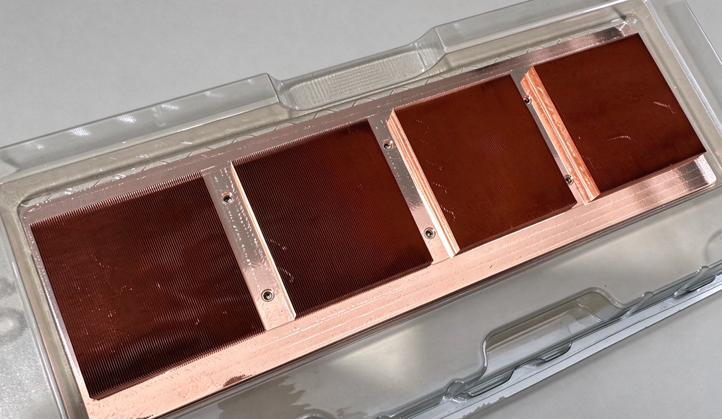
NVIDIA NVL72 is such a rack-scale architecture product. Seventy-two GPUs form a high-speed interconnect domain within one rack, with unified power and liquid cooling systems configured across the whole enclosure. Vera Rubin has entered mass production. This article disassembles the physical structure layer by layer, and outlines the modules, signal paths, power delivery paths and cooling loops of the complete Vera Rubin NVL72 system. KENFA TECH, a manufacturer specializing in cold plates and heat sinks, delivers matching thermal hardware for this high-density AI rack architecture.
Article Highlights
- 18 Compute Trays housing 72 Rubin GPUs with HBM4 and SOCAMM memory
- NVLink 6 full-mesh interconnect backbone with NVLink Spine copper cabling
- 54V liquid-cooled busbar power delivery + Intelligent Power Smoothing
- Direct liquid cooling loop with CDU, rack manifold, tray manifold and cold plates
- Tier definition: L10 standalone server, L11 full rack, L12 multi-rack AI cluster
1. 18 Compute Trays Host 72 GPUs
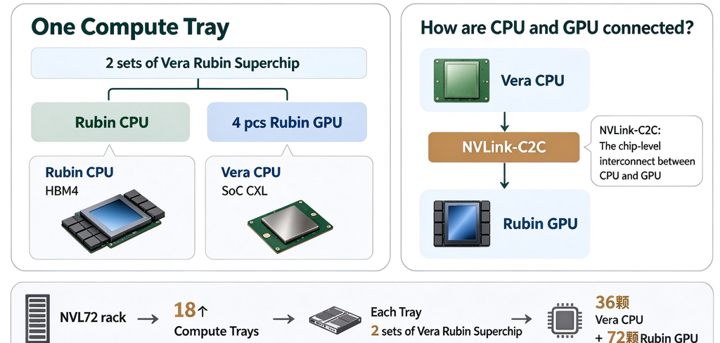
Vera Rubin NVL72 is built on the 3rd‑generation NVIDIA MGX single‑wide rack. The full rack holds 18 Compute Trays and 9 NVLink Switch Trays, with a total of 36 Vera CPUs and 72 Rubin GPUs. The system contains roughly 1.3 million components, nearly 1,300 chips, and weighs approximately 4,000 pounds (1.8 tons).
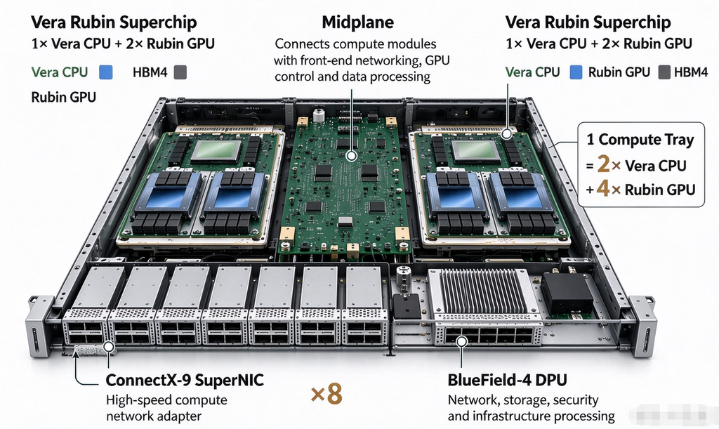
Each Compute Tray accommodates two Vera Rubin Superchip sets. One set consists of one Vera CPU paired with two Rubin GPUs. A single tray carries two Vera CPUs and four Rubin GPUs. With 18 trays assembled, the full rack delivers 36 CPUs and 72 GPUs.
Compute hierarchy chain NVL72 Rack → 18 Compute Trays → 2 Vera Rubin Superchip sets per Tray → 1 Vera CPU + 2 Rubin GPUs per set
The Vera CPU connects to the two Rubin GPUs liquid cooling plates in its set via 2nd‑generation NVLink Chip‑to‑Chip (NVLink‑C2C). NVLink‑C2C handles CPU‑GPU data exchange inside one compute module. Wider‑range GPU interconnections across modules and trays rely on 6th‑generation NVLink, which will be covered later.
1.1 Memory Configuration
Two independent memory subsystems are deployed:
- Rubin GPU: Equipped with HBM4 high‑bandwidth memory, up to 288GB per GPU
- Vera CPU: Uses SOCAMM (Small Outline Compression Attached Memory Module). The underlying medium is LPDDR5X, serving as system memory for the CPU.
GPU‑side memory supports AI compute workloads, while CPU‑side SOCAMM memory manages system control and scheduling.
1.2 Network Adapters, DPU and Midplane
Each Compute Tray includes eight ConnectX‑9 SuperNICs and one BlueField‑4 DPU. ConnectX‑9 provides high‑speed compute network access. BlueField‑4 DPU processes workloads related to networking, storage, security and infrastructure.
The core PCB inside each Compute Tray is the Midplane. Two Vera Rubin compute modules link through the Midplane to modular slots at the front for ConnectX‑9 and BlueField‑4. Many internal signals that once required separate cabling travel through PCB traces and connectors instead, cutting cable count inside the tray.
Internal tray signal path Vera CPU / Rubin GPU compute module → Midplane → Front‑end modules including ConnectX‑9 and BlueField‑4
The Midplane resides only within one Compute Tray and is not a large backplane spanning the full NVL72 rack. This layout simplifies internal tray wiring, though cross‑tray connections across the rack still require extensive high‑speed copper cables.
How are the 72 Rubin GPUs interconnected?
2. 72 GPUs Fabric the Interconnect Network via NVLink
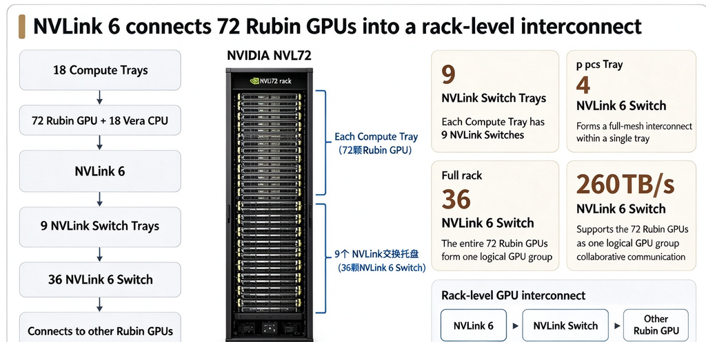
Within one compute module, CPUs and GPUs communicate over NVLink‑C2C. At rack level, 72 Rubin GPUs achieve full mesh connectivity using 6th‑generation NVLink and NVLink Switches.
Vera Rubin NVL72 incorporates nine NVLink Switch Trays, each fitted with four NVLink 6 Switch chips, for a total of 36 switch chips across the rack. NVLink 6 delivers 260 TB/s of rack‑level aggregate bandwidth, forming a unified high‑speed compute domain for all 72 GPUs.
GPU data transfer path Rubin GPU → NVLink 6 → NVLink Switch → Other Rubin GPUs
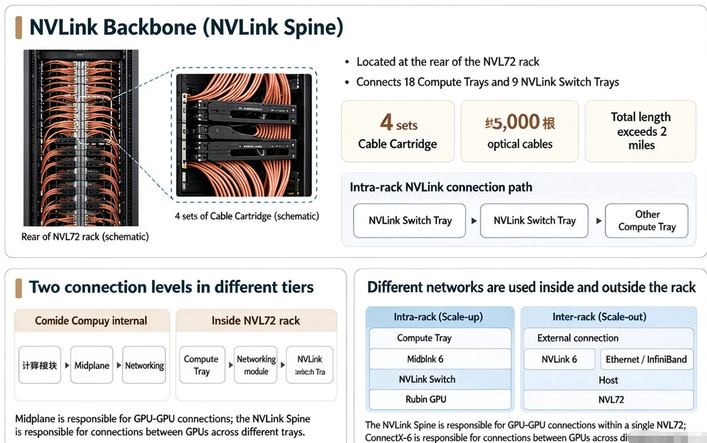
NVLink cabling runs mainly at the rear of the rack. The NVLink Spine serves as the main interconnect backbone, assembled from four modular pre‑terminated Cable Cartridges. It contains roughly 5,000 copper cables with a total length exceeding two miles, linking the 18 Compute Trays and 9 NVLink Switch Trays.
Two distinct high‑speed interconnect schemes coexist in the system with clear functional separation:
- Inside Compute Tray: Compute module → Midplane → Network module (PCB‑based interconnection)
- Cross‑tray within NVL72 rack: Compute Tray → NVLink copper cable → NVLink Switch Tray
The Midplane handles signal routing inside each tray; the NVLink Spine carries rack‑scale high‑speed links between compute trays and switch trays. The NVLink Switch Tray is an independent, serviceable modular unit with four NVLink 6 Switch chips. It can enter maintenance mode individually while the rest of the rack continues operation.
Two network domains
- Intra‑rack domain: GPU ↔ NVLink ↔ NVSwitch ↔ GPU (NVLink for GPU communication inside one rack)
- Inter‑rack domain: Compute Tray → ConnectX‑9 → Spectrum‑X Ethernet / Quantum‑X800 InfiniBand → Other NVL72 racks (Ethernet / InfiniBand for multi‑rack cluster expansion)
NVLink only carries GPU traffic within a single NVL72 rack. ConnectX‑9 and external switching networks manage data exchange between separate NVL72 racks.
How Is Power Delivered to the Rubin GPU?
3. Power Delivery Path: Power Travels from Power Shelf to GPUs
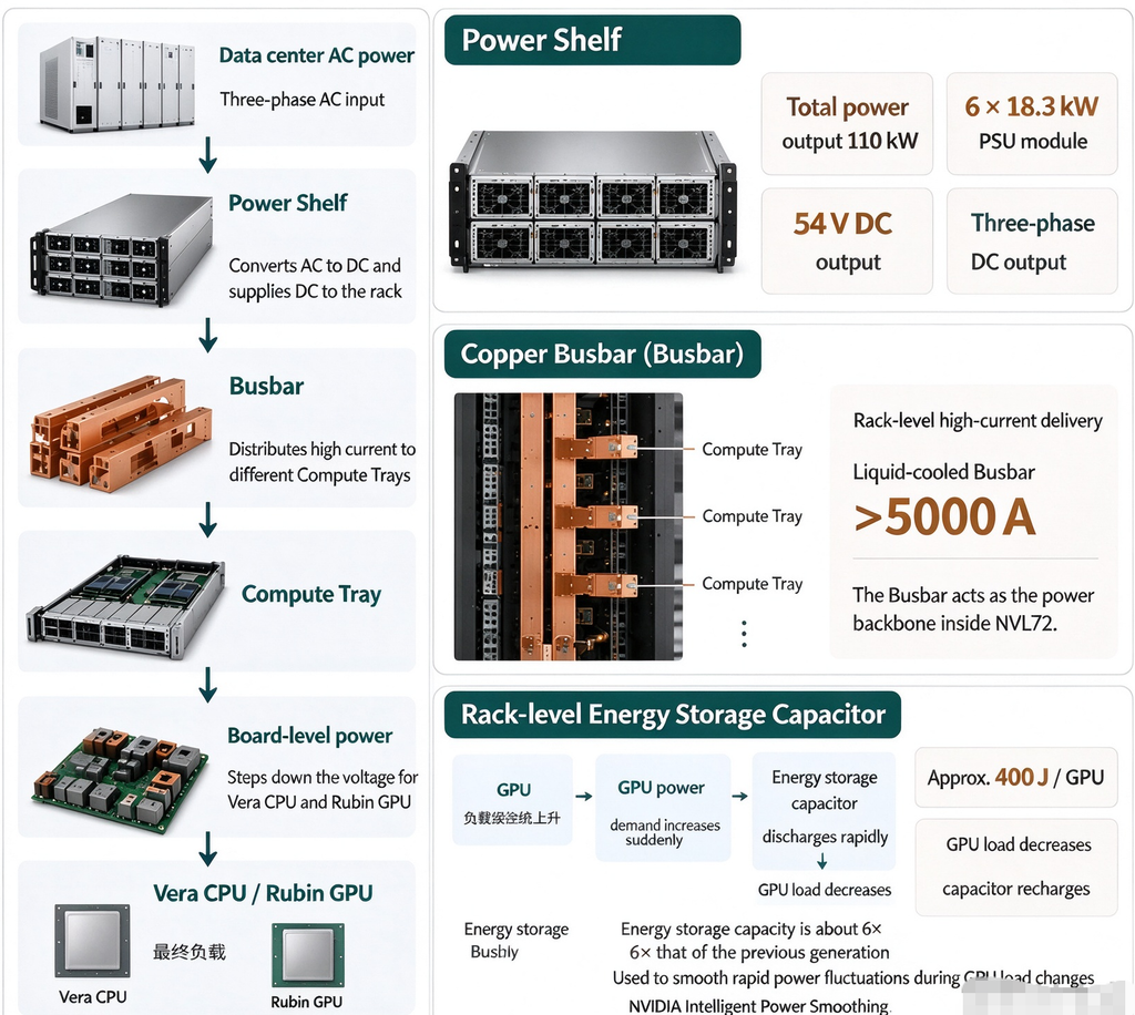
Vera Rubin NVL72 implements a complete rack‑scale power system. Power flow path: Data center AC → Power Shelf → Busbar → Compute Tray → On‑board power converters → CPUs / GPUs
The Power Shelf executes AC‑DC conversion and turns incoming AC power into DC for rack consumption. The Rubin Power Shelf shown at GTC2026 follows a 3RU, 19‑inch form factor, rated at 110 kW total. It comprises six 18.3 kW PSUs, accepts three‑phase AC input, and raises the DC output voltage to 54 V from the prior 50 V generation.
Converted DC power feeds into the copper busbar. The busbar acts as the main high‑current power backbone inside the rack, distributing power to every Compute Tray and other assemblies. After power enters a Compute Tray, on‑board converters step down voltage to match the requirements of CPUs, GPUs, memory and network chips.
The busbar on the 3rd‑generation MGX rack integrates into the liquid cooling loop. This Liquid‑Cooled Busbar supports up to approximately 5,000 A. Beyond the Power Shelf and busbar, the rack includes rack‑scale energy storage capacitors. GPU power draw fluctuates rapidly under dynamic AI loads. Capacitors discharge during power spikes and recharge as load drops, mitigating power surges back to the upstream grid. NVIDIA names this mechanism Intelligent Power Smoothing. The Vera Rubin NVL72 storage design targets roughly 400 J per GPU, with total energy capacity six times that of the prior generation.
Summary of the main Rubin power path: Power Shelf performs conversion → Busbar distributes power → On‑board converters supply regulated voltage to chips. Rack storage capacitors buffer instantaneous power swings in parallel.
How Does Coolant Flow to the Rubin GPU?
4. Liquid Cooling Path: Coolant Flows from Outside the Rack to CPUs and GPUs
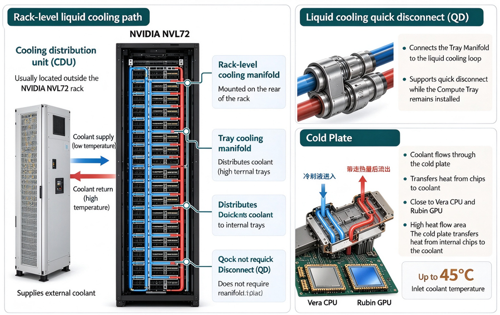
Vera Rubin NVL72 adopts direct liquid cooling. The maximum design inlet temperature for rack coolant is 45 °C.
Full coolant flow path Cooling Distribution Unit (CDU) → Rack Manifold → Tray Manifold → Quick Disconnect (QD) → Cold Plate → CPU / GPU
The CDU is normally placed outside or beside the rack. It circulates coolant and exchanges heat with the facility cooling system. Rack‑internal liquid cooling components and side‑car CDU are listed separately in the system BOM.
Coolant enters the rack and first reaches the Rack Manifold, which works as a water separator to divert fluid from the main loop to individual Compute Trays. Inside each tray, the Tray Manifold further splits flow to hot components. The 3rd‑generation MGX rack ships with redesigned internal Tray Manifolds and Rack UQD08 Manifolds.
Liquid lines use Quick Disconnect (QD) fittings. QDs allow isolation of one tray’s cooling loop. Service teams can replace a Compute Tray without draining or disassembling the full rack piping. Coolant finally passes through cold plates bonded to high‑power devices including Vera CPUs and Rubin GPUs. Heat from chips transfers into cold plates and is carried away by circulating coolant before returning out of the rack.
Two parallel backbone systems run inside the rack:
- Power path: Power Shelf → Busbar → Compute Tray → Chips
- Liquid cooling path: Rack Manifold → Tray Manifold → QD → Cold Plate → Chips
One delivers electricity, the other removes waste heat. KENFA TECH supplies high‑performance cold plates and heat sinks optimized for such high heat flux AI hardware.
5. From a Single Rubin NVL72 to L12 Cluster Hierarchy
Once 18 Compute Trays, 9 NVLink Switch Trays, NVLink Spine, Power Shelf, Busbar, liquid cooling piping and other rack components are installed and validated, one Vera Rubin NVL72 forms a complete rack‑scale compute system.
Standard industry tier definitions
- L10: Independent standalone server
- L11: Fully integrated deployable rack combining servers, switches, power supplies, liquid cooling and cabling. Vera Rubin NVL72 falls into L11.
- L12: Cluster‑level integration. The scope expands beyond one rack to an AI cluster built from multiple NVL72 racks.
L12 cluster integration includes cross‑rack Ethernet / InfiniBand deployment, management network configuration, unified OS, driver and firmware rollout, plus validation of network throughput, GPU collective communication, storage performance and long‑term stability.
Conclusion
Vera Rubin NVL72 represents a new generation of rack‑scale AI compute architecture, breaking the design limits of traditional standalone servers. The system takes the Compute Tray as its minimum compute unit. It builds a full‑mesh intra‑rack GPU network over NVLink 6, paired with dedicated rack‑scale cooled busbars plus power smoothing capacitors and direct liquid cooling loops. This unifies compute, interconnect, power delivery and thermal management in one platform.
The architecture delivers a standardized L11 full rack building block for L12 large‑scale AI cluster deployment, suited for large model training and high‑performance computing. On thermal management, cold plates and liquid‑cooled busbars jointly handle heat from high‑power chips and high‑current bus conductors. This is a representative thermal solution for ultra‑high‑density AI racks.
KENFA TECH focuses on manufacturing cold plates and heat sinks, supporting the thermal requirements of next‑generation AI rack systems.So you can email to us king@kenfatech.com or linkedin