1,Why we wrote this article on thermal management for robots
We publish this article on robotic thermal management to equip our engineers with a complete thermal design workflow and solution framework. We hope this content delivers practical value to engineers in daily project work.As end-side large models develop rapidly, AI robots are moving from demo prototypes toward mass deployment. Humanoid robots, inspection robots, mobile manipulation robots and industrial collaborative robots no longer carry heat from a single main processor. Instead, they operate as distributed multi-heat-source coupled systems: main SoC, NPU, servo motors, reducers, drive boards, battery packs, LiDAR, image sensors and DCDC converters all generate heat inside a compact enclosed chassis.
Traditional cooling solutions built for single chips, such as standard extruded heat sinks and fan-based air cooling, can no longer satisfy these operating conditions. Thermal crosstalk between heat sources, superimposed temperature fields and shifting hotspots lead to cascading issues including NPU throttling, servo drift, accelerated battery degradation, sensor thermal drift and reduced reliability.
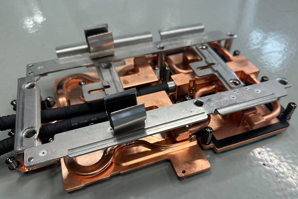
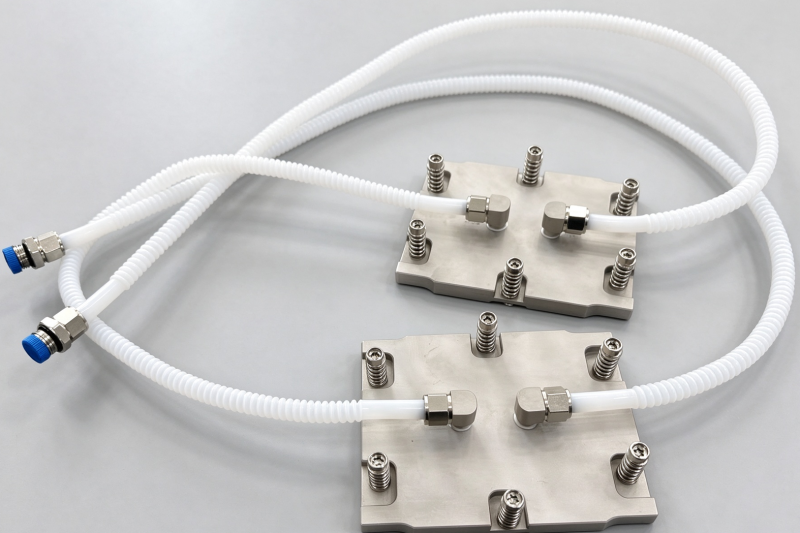
A well-known observation from the 2026 humanoid robot marathon illustrates this limitation clearly. Many robots maintain stable locomotion over the first kilometer, yet lose posture balance and fall frequently in mid-to-late stages of the race. The root cause is not inadequate mechanical hardware, but insufficient thermal control. Battery-powered robots are highly vulnerable to elevated temperature, which is a key limitation for stable operation and a major barrier to long-duration continuous operation in real-world scenarios. Our engineering team at Kenfa Tech has developed a liquid cold plate circulation system built around an original liquid cooling framework. A single main pump governs cold plates with multiple independent channels. Cold plate dimensions are determined by flow regulation and the power load of heat-generating joint components. Industry reports indicate approximately 90% of the energy consumed by humanoid robots converts into waste heat, trapped in tight spaces around motor windings, gearboxes and chips. Thermal management has become the next critical bottleneck for AI deployment.
Although robot liquid cooling and datacenter liquid cooling share the same “liquid cooling” label, their design priorities differ substantially. Robots operate under extreme space constraints, strict weight limits and rapidly shifting dynamic loads. Joint motors release transient heat during heavy lifting, compute modules run continuously, and battery packs demand consistent temperature uniformity. Design frameworks proven for server liquid cooling cannot be directly applied to robotic systems.
Unlike centralized cooling in server racks, AI robots face rigid constraints: weight budgets, compact packaging, vibration under dynamic movement, low-noise requirements and IP protection grades. Fan-heavy designs are often undesirable. Multi-heat-source coupling has become a core factor limiting the performance and service life of high-performance AI robots.
2 Characteristics and Classification of Heat Sources Inside AI Robots
Heat sources in robotic systems are not merely separate heat-generating parts. Four unique traits make robotic thermal design especially challenging:
- Wide power range across heat sources Power dissipation spans from less than one watt for sensors and MCUs, to tens or over one hundred watts for end-side NPUs and SoCs, plus dynamically varying servo motor loads. Heat from high-power components easily propagates to nearby temperature-sensitive devices. For example, LiDAR placed close to an NPU often only tolerates a narrow ±5 ℃ temperature window and suffers measurement drift when exposed to conducted heat.
- Spatially scattered, heterogeneous heat distribution Heat sources spread across the torso, head and joints rather than concentrating on one PCB. Rotary joint motors create interrupted thermal conduction paths and cannot be covered by one large monolithic cold plate. Compute boards sit in the torso while battery packs are mounted separately, separated by structural frames, wiring and sealed enclosures with complex thermal resistance boundaries.
- Unsynchronized transient heat generation Heat loads activate at different times: standby mode, vision inference, large-model computation, fast walking and grasping tasks trigger separate heat sources. At one moment only the NPU may run at high load; moments later multiple servo motors peak simultaneously. Temperature fields rearrange continuously, so steady-state simulation results diverge significantly from real operating conditions.
- Tight packaging limits for cooling paths Humanoid enclosures require IP ratings, ruling out large ventilation cutouts. Weight targets restrict the overall size of heat sinks. Pipes and heat pipes risk mechanical interference as joints rotate.
| Component | Typical Power | Max Allowable Temperature | Thermal Characteristics |
|---|---|---|---|
| End-side NPU / SoC | 30–120 W | 85 ℃ | Pulsed high load, localized hotspots |
| Joint servo motor + driver | 8–40 W per axis | 105 ℃ | Dynamic load, rotary assembly |
| Lithium battery pack | 5–20 W | 45 ℃ | Sensitive to temperature rise and delta-T |
| LiDAR / vision sensor | 1–5 W | 0 ~ 50 ℃ | Thermal drift directly degrades precision |
| DCDC power module | 3–10 W | 90 ℃ | Distributed, numerous small heat sources |
3 Core Engineering Challenges from Coupled Multi Heat Sources
3.1 Thermal Crosstalk and Hotspot Migration
Single-component cooling only targets junction temperature. In multi-source systems, heat transfers to adjacent sensitive parts through solid conduction and internal air convection. Hotspots identified under steady-state conditions shift as the robot changes posture and load. Fixed heat sinks optimized for one operating point often fail when the working state changes, creating a trade-off where cooling for one region worsens temperature elsewhere.
3.2 Conflicting Temperature Window Requirements
This is the most prominent contradiction. Compute chips tolerate higher temperatures, while batteries and optical sensors have narrow thermal limits. If cooling is prioritized for the NPU, nearby precision devices overheat. If battery and sensor protection becomes the primary goal, cooling hardware grows too large and costly. Air cooling rarely enables independent zoning control.
3.3 Thermal Transport Barriers from Rotary Joints
Rotary joints present the hardest challenge. Heat builds in motor stators and windings, while the rotary interface introduces high contact resistance. Standard static cold plates do not adapt to continuous rotation. Flexible tubing carries risks of fatigue and leakage after prolonged vibration.
3.4 Rising Complexity of System-Level Thermal Simulation
Single chips only require localized simulation. Multi-source robot thermal analysis must combine electrical load, robot kinematics, solid conduction and internal natural convection, with boundary conditions changing with motion. Standalone steady-state Icepak simulation cannot fully cover operational envelopes. Co-simulation cycles are long and rely heavily on experienced engineers, pushing up iteration cost in early design stages.
3.5 Three-Way Trade-off Between Noise, Weight and Power Consumption
Additional fans improve air cooling but introduce noise, vibration, extra power draw and compromise IP protection. Heat pipes keep weight low but cannot isolate heat sources; shared vapor chambers create cross-thermal interference and have upper heat flux limits. Liquid cooling delivers high heat transfer capacity yet adds pumps, tubing and fittings, bringing weight and leakage-control requirements.
4 Mainstream Thermal Solutions and Their Limitations
4.1 Air Cooling with Distributed Heat Sinks (Extruded / Skived Fin Heat Sinks)
Concept: Each heat source is fitted with a dedicated small heat sink, paired with passive internal convection or auxiliary miniature fans.
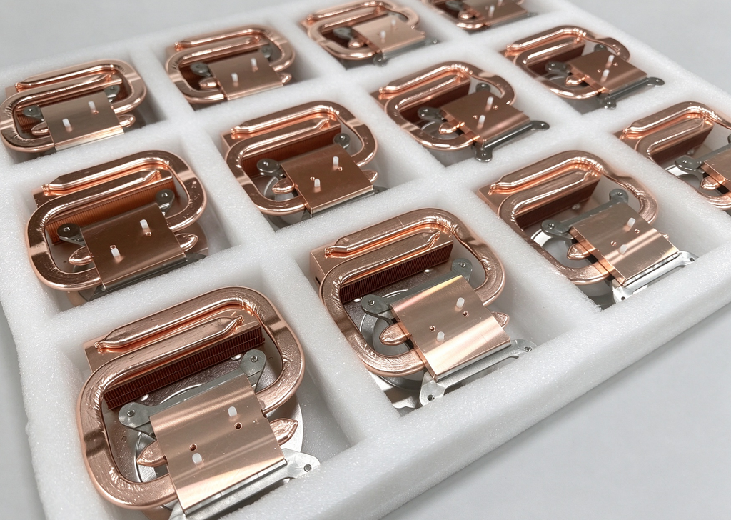
✅ Advantages: Low cost, simple assembly, zero leakage risk, easy service. Skived fin structures achieve high fin density and large local heat exchange area.
❌ Limitations: Poor internal air convection efficiency; thermal crosstalk cannot be suppressed; insufficient margin for high-power NPUs; fan noise and ingress protection weaknesses; no independent zoning temperature control. Best fit: Low-power inspection robots and lightweight collaborative robots.
4.2 Heat Pipe Heat Spreading
Concept: Heat pipes attach to individual heat sources and route waste heat to a remote radiator.
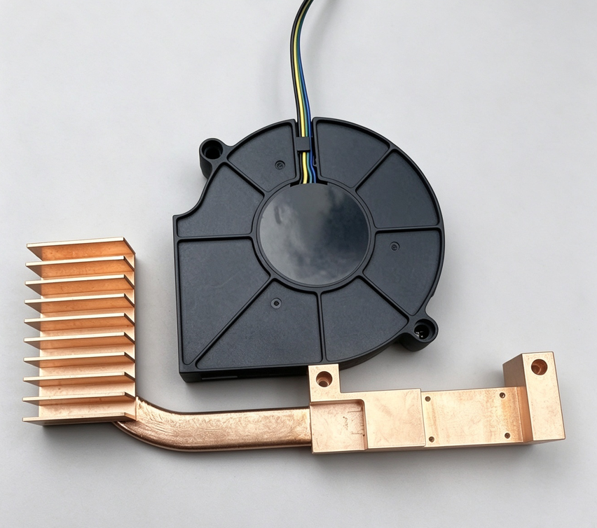
✅ Advantages: Lightweight, near-isothermal performance, no moving parts. Suitable for gathering heat from joints and main boards toward rear-mounted radiators.
❌ Limitations: Heat pipes transfer heat but do not isolate sources; shared vapor spreaders cause crosstalk; bending and packaging constraints limit joint deployment; maximum heat flux ceiling.
4.3 Distributed Cold Plate Solution
Concept: Custom cold plates with isolated internal channels for individual high-power heat sources, preventing cross-heat transfer between loops.
✅ Advantages: Strong heat removal capacity, zoning temperature control possible. Channels are customizable for irregular robotic geometries; friction stir welding and vacuum brazing support complex cold plate designs for loads up to 100 W and above.
❌ Limitations: Requires pumps, tubing and fittings; routing around rotary joints is difficult; higher cost than air cooling or heat pipes; leak testing and helium leak check are mandatory.
4.4 TEC Thermoelectric Cooling Modules for Precision Local Control
Concept: TEC modules provide active cooling for temperature-critical low-power devices such as cameras and LiDAR, decoupling these components from the passive cooling loop serving NPUs and motors.
✅ Advantages: Closed-loop active temperature stabilization, immune to heat spillover from nearby high-power hardware.
❌ Limitations: Low coefficient of performance at high power; the hot side of each TEC still needs a matched heat sink; extra drive circuitry is required.
Recommended combined architecture from our team: Custom cold plates for high-power NPUs + skived fin heat sinks for servo motors + independent TEC assemblies for optical sensors, with thermal gaskets and insulation spacers between heat zones to decouple thermal crosstalk.
5 Design Principles for Multi-Heat-Source Robot Thermal Management
- Prioritize thermal decoupling over one unified cooling path Avoid relying on a single cooling subsystem for all heat loads. Use structural insulation and separated loops first to block heat transfer from high-power zones to sensitive components.
- Classify components by temperature tolerance and define thermal boundaries Group hardware into high-temperature zone (compute chips, motor drivers), mid-temperature zone (power converters) and low-temperature precision zone (LiDAR, optics, batteries), with independent cooling limits for each group.
- Reserve thermal margin for dynamic peak loads, do not size hardware only on steady-state simulation Include short peak-load profiles in simulation and reserve temperature headroom. A design valid under steady-state conditions may fail under transient robot motion.
- Reduce contact resistance at rotary joints and minimize fluid lines through rotating interfaces Select high-performance skived fin heat sinks and thermal interface materials for joint motors wherever feasible. Limit flexible liquid lines across rotary axes to reduce long-term vibration-induced failure.
- Integrate thermal requirements in early DFM together with mechanical packaging Thermal hardware should not be retrofitted after mechanical design locks. Thermal assessment must run alongside layout, enclosure sealing and weight budgeting.
6 ,What can kenfa tech can help your thermal projects?
Thermal design for next-generation humanoid and embodied robots is evolving from component-level cooling to full-system thermal orchestration. No single cooling component solves all requirements; successful designs combine passive spreading, liquid cooling, precision TEC modules and thermal isolation, coordinated by control logic. The core challenge of multi-source thermal coupling arises from overlapping heat flows, conflicting temperature limits and robotic motion constraints. As end-side compute power rises, demand grows for decoupled multi-zone cooling, custom-shaped cold plates, high-density skived fin heat sinks and compact TEC assemblies. This opens significant opportunities for specialized thermal hardware manufacturers.
Kenfa Tech is a full-stack thermal management manufacturer. Beyond thermal design capability, we supply cost-effective and reliable heat sinks and cold plates to match project requirements. If you are developing multi-source thermal solutions for humanoid or embodied robots, feel free to reach out for preliminary thermal assessment and sample support.So you can email to us king@kenfatech.com or +our engineer Whatsapp +86 13922909212