
Abstract
Our purpose for this article is to help our customers and thermal engineers avoid common pitfalls during thermal simulation analysis. This allows them to complete early-stage R&D design rapidly.Liquid cold plates serve as core thermal management components for high-heat-flux devices including IGBTs, optical modules and AI servers. Icepak-based CFD simulation is widely adopted to predict chip junction temperature and channel pressure drop. However, significant discrepancies often exist between simulation outputs and experimental measurements. This paper identifies five frequent pre-processing defects that dominate temperature and pressure mismatch: improper geometric simplification, incomplete fluid domain extraction, unreasonable meshing strategy, unit conversion errors at inlet boundaries, and false convergence judged solely by residuals. Results show that strict implementation of this standardized preprocessing specification can raise the consistency between simulation and experimental data above 80%, limit temperature deviation within 10 K, and substantially reduce pressure-drop error. This work provides a repeatable preprocessing workflow for thermal engineers working on liquid cold plates with dense fins and irregular channels.
Introduction
High-density electronics such as IGBT power modules and AI accelerators impose strict thermal constraints, and liquid cold plates are the mainstream thermal control hardware. Computational fluid dynamics simulation has become a standard method to evaluate thermal and hydraulic performance before prototyping¹. In engineering practice, many simulations deliver unreasonable results: predicted chip temperature exceeds measured data by over 10 °C, and pressure drift reaches 20 kPa. Deviations persist even after mesh refinement and extended iterations. Such mismatches are commonly attributed to solver settings rather than upstream pre-processing.
For complex cold plates with double-sided component mounting, dense fins and CAD-derived irregular channels, simulation reliability is fundamentally governed by preprocessing quality. This paper isolates five dominant error sources and establishes a validated preprocessing specification to reduce systematic deviation between simulation and experiment.
The most prominent challenge in complex liquid cold plate simulation is not divergence, but persistent mismatch between simulation values and test data: chip temperature deviation can reach 10 °C and pressure-drop deviation up to 20 kPa. The deviation remains even with continuous mesh refinement and extra iterations. Root causes lie in preprocessing rather than the solver itself.
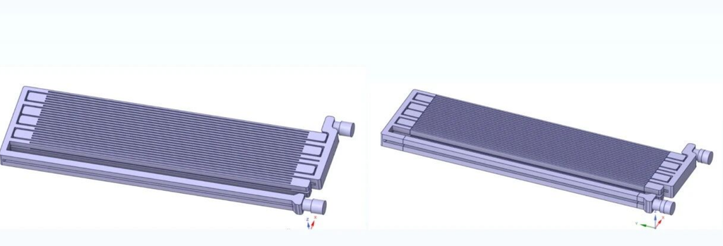
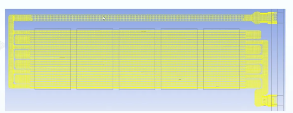
1,What is the root cause of the error when do the thermal solutions?
The five independent error sources can overlap and amplify deviations:
- Excessive redundant geometric features fragment the model, leading to distorted meshes and inflated cell counts.
- Incomplete or interfered fluid domains, missing flow passages, mixed liquid-air domains, which easily trigger divergence.
- Global uniform meshing strategy fails to fit boundary layers on channel walls, causing distorted velocity and pressure predictions.
- Confusion between flow rate and flow velocity, wrong unit conversion, which renders boundary conditions invalid.
- Convergence judged only by residual curves without temperature monitoring; residuals may converge while temperature keeps drifting, resulting in false convergence.
2,How can we standardize operations during the design process?
- Geometry cleanup: Do not import models directly into Icepak; process files in SpaceClaim first STEP or X_T files should not be loaded into Icepak directly. Import files into SpaceClaim for model simplification. Suppress minor non-thermal features such as small screw holes, positioning bosses and tiny chamfers, and retain only the cold plate solid body and internal flow passages. Benefit: Total mesh volume can be reduced by more than 30%. For aluminium cold plates, thermal conductivity is set at approximately 200 W·m⁻¹·K⁻¹. If TIM thermal grease exists between heat source and cold plate, contact thermal resistance must be defined. Direct face bonding underestimates junction temperature by 5–8 °C.
- Fluid domain extraction: full enclosure + segmented cutting, no missing flow sections The fluid domain must fully cover manifolds, distribution chambers, dense fin channels and collecting chambers. Segment the domain along flow paths for clear boundaries between fluid blocks. Avoid wrapping the solid cold plate with a simple rectangular fluid block from Icepak, which often causes geometric interference at irregular channel corners and negative volume errors. Standard workflow: Extract fluid bodies from inner cold plate surfaces inside SpaceClaim and partition along flow paths. Assign separate fluid material after importing into Icepak. Strictly isolate water and air domains; mixed liquid-air domains are the leading cause of convergence failure.
- Meshing strategy: Avoid global refinement; use Mesher-HD multi-level mesh Default staggered meshes cannot capture boundary layers for dense and irregular channels. Mesher-HD unstructured multi-level mesh is preferred. Key parameters: Mesh quality between 0.3 and 0.5. Values below 0.2 raise negative volume risk; values above 0.8 waste computing resources. Set the first boundary layer height for y+≈1. Calculate Reynolds number in advance to distinguish laminar and turbulent regimes and confirm whether wall functions are required. Apply local refinement on fluid domains while using coarser meshes for solid bodies. Each flow cross-section contains at least 5–8 mesh layers. The economical total cell count ranges from 3 million to 8 million.
- Boundary conditions: Accurate unit conversion, distinguish L/min from m/s Flow rate marked on pump nameplates in L/min cannot be directly used as velocity in m/s. Conversion formula: Volumetric flow rate (m³/s) = L/min × 10⁻³ ÷ 60; Flow velocity = volumetric flow rate ÷ inlet cross-sectional area. Case reference: Coolant is 53% ethylene glycol aqueous solution, inlet temperature 45 °C. Six IGBT heat sources, 2000 W per unit, total heat load 12000 W, heat flux 10–50 W·cm⁻². At early design stages, a heat exchanger lumped resistance model can be adopted for fast iteration. Switch to full detailed geometry once the channel topology is finalized.
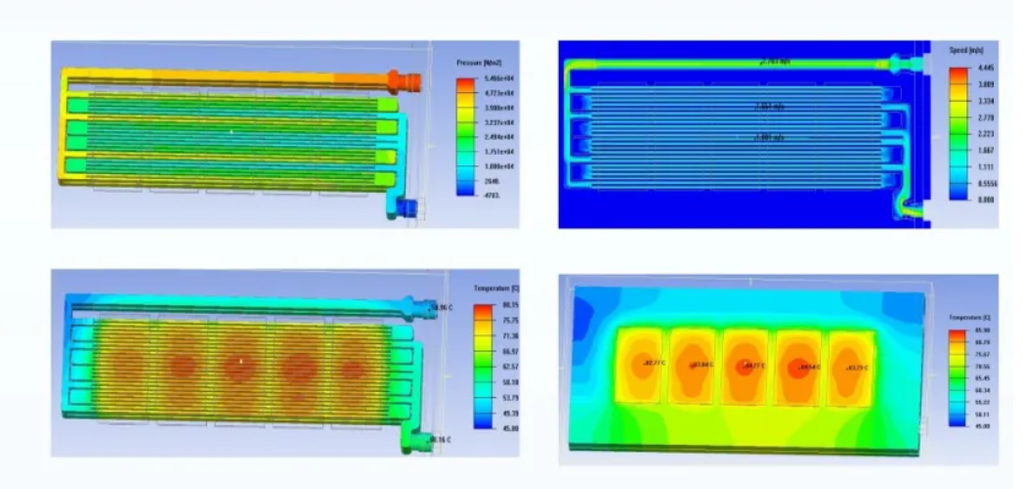
- Convergence criteria: Do not rely only on residuals; stable temperature readings at heat source monitors are required Steady-state simulation with combined forced liquid cooling ,heat sinks and natural convection. Residual dropping to 1e-5 is only a prerequisite. Place temperature monitors on each IGBT heat source. Convergence is confirmed only when monitored temperature fluctuates less than 0.1 °C over 200 consecutive iterations. Key post-processing metrics: total fluid pressure drop, velocity distribution and dead zone identification, inlet-outlet temperature rise, maximum surface temperature of heat sources. Under this specification, peak heat source temperature is around 85 °C and temperature rise across the cold plate is approximately 10 °C, matching experimental results.
3,Analysis of the comparison table
| Improper preprocessing method | Standard preprocessing method | Result difference |
|---|---|---|
| Import STEP directly into Icepak and keep all tiny features | Simplify geometry in SpaceClaim and suppress non-thermal features | Bulky, distorted meshes and large temperature deviation / Clean mesh, faster simulation and controlled error |
| Wrap solid part with a simple fluid block without separate extraction | Extract fluid domain from inner surfaces and partition along flow paths | Easy interference, negative volume and divergence / Complete flow channels, clear boundaries and stable convergence |
| Global uniform mesh refinement | Mesher-HD multi-level mesh with local refinement on fluid region | Wasted computing power and inaccurate wall pressure / Well-fitted channel boundary, pressure and velocity close to test data |
| Take L/min directly as flow velocity input | Convert flow rate to volumetric flow and calculate velocity separately | Velocity overestimated by dozens of times, heavily distorted pressure drop / Boundary conditions match actual working conditions |
| Terminate calculation once residuals converge | Dual criteria: residual + stable temperature monitors | False convergence with drifting temperature / True convergence with reliable temperature results |
This specification applies to Icepak steady-state thermal simulation for liquid cold plates used in AI computing, IGBT, CPO optical modules, laser and radar thermal systems, and high-density server heat sinks. It supports preliminary design iteration, simulation-to-test benchmarking, experimental data reconstruction and thermal design validation.
4,Discussion
Geometry preprocessing. Import STEP models into SpaceClaim; suppress non-functional geometry including small mounting holes, positioning protrusions and tiny chamfers; separate solid and fluid domains; extract fluid domains from inner walls and partition along flow paths.
Numerical setup. Steady-state CFD solved in Icepak. Aluminium thermal conductivity = 200 W·m⁻¹·K⁻¹. TIM contact resistance defined at heat source-cold plate interfaces. Coolant: 53% ethylene glycol aqueous solution. Mesher-HD mesh, quality 0.3–0.5, y+≈1.Convergence criteria. Continuity residual <10⁻⁵; temperature monitors on each heat source with fluctuation <0.1 °C over 200 iterations.Post-processing outputs. Pressure drop, velocity distribution, inlet-outlet temperature rise, maximum heat source temperature.
This study demonstrates that simulation deviation mainly comes from human-induced preprocessing errors rather than solver precision. The five types of defects are independent and can compound together. Pure mesh refinement cannot compensate incomplete fluid domains, missing TIM contact resistance or wrong boundary assignments. The specification proposed here achieves over 80% consistency between simulation and test for cold plates with dense fins and irregular channels. Remaining deviation can be further reduced through gradual mesh refinement and TIM contact resistance calibration.This work covers only steady-state forced liquid cooling. Transient behaviour and two-phase flow are not included. Future work will extend this preprocessing framework to phase-change cooling and embedded microchannel designs.
5,Technical Q&A
Q1: Why does the gap between simulation and test become larger after mesh refinement?
A: This is usually caused by uncleaned geometry, fluid domain interference or missing TIM contact resistance. Mesh refinement cannot fix upstream modelling errors; it only amplifies them.
Q2: Must the mesh count reach 8 million for cold plates with skived fins and crossed irregular channels?
A: Not necessarily. If each flow cross-section has 5–8 mesh layers, reliable results can be obtained at 3–5 million cells after proper simplification of non-thermal features. Mesh quality takes priority over total cell count.
Q3: If simulated pressure drop differs greatly from test data, which item should be checked first?
A: Check flow rate unit conversion, completeness of fluid domain extraction and tiny gaps at channel corners first. Then verify fluid viscosity and coolant mixing ratio.
What Can we help you in the thermal design?
Through this article, we share our engineers’ practical design experience to help you avoid frequent pitfalls in thermal simulation. Following this standardized preprocessing specification can reduce repeated debugging and shorten the iteration cycle in early R&D. The thermal R&D team of KENFA TECH can support you with liquid cold plate simulation benchmarking, sample testing and customized thermal design solutions for high-heat-flux devices. Feel free to email us at king@kenfatech.com if you have better ideas or design proposals for joint discussion.