
Abstract
This article is written to help engineers gain a deeper understanding of the Vera Rubin NVL72 architecture.Following our previous article covering the full mechanical disassembly of Vera Rubin NVL72, this post breaks down the single-phase direct liquid cooling (DLC) system of this platform layer by layer. Both GB300 NVL72 and Vera Rubin NVL72 are equipped with 72 GPUs, yet the overall thermal load rises significantly. GB300 NVL72 supports a maximum cabinet power of approximately 142 kW, while Vera Rubin NVL72 is designed for DSX facility infrastructure with a peak cabinet thermal rating of 330 kW. Rubin NVL72 adopts 100% rack-level liquid cooling with 45°C warm-water single-phase direct liquid cooling (DLC). GPUs, CPUs, switch chips, network components and power busbars are all integrated into a closed coolant loop, with no internal rack fans. This article follows the coolant flow path from CDU to cold plate, mapping the complete circulation system, with supplementary engineering details including solution comparison, cold plate processes, connector specifications, operation risks.
1. System Overview: 45°C Warm-Water Single-Phase Direct Liquid Cooling Architecture
The core feature of this design is the 45°C warm inlet coolant. This value refers to the coolant temperature entering the server-side liquid cooling loop, not the junction temperature of GPUs or CPUs. Chip temperature stays higher than coolant temperature, and heat transfers continuously to the cold plate via temperature difference. The 45°C warm-water design reduces reliance on low-temperature chilled water for data centers. Under favorable ambient conditions, the facility-side loop can reject heat directly to the outdoors via dry coolers, cutting chiller runtime and lowering PUE. The system contains two independent circulation loops:
- Server-Side Closed Loop: Coolant circulates between trays and CDU within the rack, with no mixing with facility water.
- Facility-Side Loop: Absorbs heat transferred from the CDU and dissipates heat to the outdoor environment.
Available coolants: Deionized Water, Propylene Glycol-Based Fluid (PG25).
Comparison Table of Liquid Cooling Solutions: Vera Rubin NVL72 / GB200 / GB300 NVL72
| Item | GB200 NVL72 | GB300 NVL72 | Vera Rubin NVL72 |
|---|---|---|---|
| Max Cabinet Power | ~90 kW | ~142 kW | 330 kW |
| Max Coolant Inlet Temp | 35°C | 40°C | 45°C (Warm-water cooling, compatible with existing CDU infrastructure) |
| Cooling Coverage | GPU primary, other components with auxiliary air cooling | GPU + partial optical modules liquid cooled, limited fans retained | Fanless trays, full liquid cooling for GPU, Vera CPU, BlueField-4, NVLink switch, power module and liquid-cooled busbar |
| Channel Layout | Independent cold plate per module, series piping | Dual-loop split, separated high/low power zones | Central rack manifold, tray-internal distribution manifold, dedicated cold plate branch for each component |
| System Pressure Drop | Low, suitable for legacy CDU | Medium, notable pressure rise at high flow | Higher, higher requirement for CDU pump head and flow regulation |
2. Coolant Path 1: CDU, Cooling Distribution Unit
Coolant first flows into the CDU (Cooling Distribution Unit), which sits between the server liquid cooling loop and data center facility cooling infrastructure. NVIDIA DSX reference design implements liquid-to-liquid CDU:
- An internal heat exchanger isolates the two fluid circuits; server-side coolant and facility water do not mix.
- It regulates server-side coolant circulation, loop flow rate and pressure.
- It transfers heat from server hardware to facility water, which carries heat to dry coolers or chillers.
3. Coolant Path 2: Rack Manifold
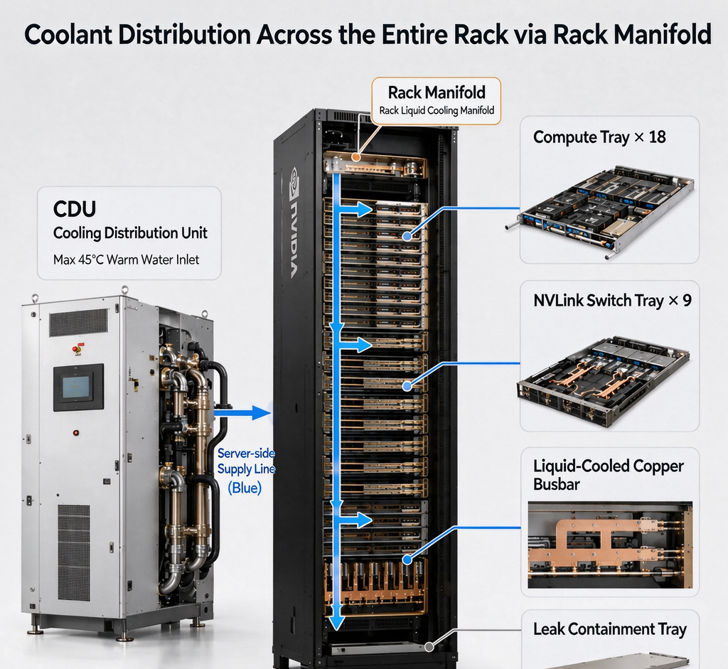
After exiting the CDU, coolant enters the rack manifold. The 3rd-generation MGX platform deploys a new UQD08 rack manifold. The rack manifold serves as the primary distribution header at rack level:
- Supply Side: Distributes coolant to individual liquid cooling trays inside the rack.
- Return Side: Collects heated coolant from all trays and routes it back to the CDU.
Rack configuration: 18 × Compute Trays 9 × NVLink Switch Trays All trays are fanless and fully liquid-cooled. The 3rd-generation MGX also integrates liquid-cooled copper busbars rated up to roughly 5000 A, removing Joule heat from high-current power transmission through liquid cooling. Safety structure: Leak Containment Tray, designed to capture leaked coolant and mitigate failure risks.
4. Coolant Path 3: UQD, Universal Quick Disconnect
The rack manifold connects to liquid cooling branches of individual trays through UQD (Universal Quick Disconnect). UQD is the core maintenance component of this system:
- It enables quick connect and disconnect for supply and return lines.
- During tray service, the tray loop can be isolated without draining or shutting down the whole rack. Coolant passes through UQD and enters the tray manifold.
UQD Specification, Seal Material, Pressure Rating
- Common sizes: UQD04, UQD08; UQD08 is standard for NVL72 racks
- Housing: 304 stainless steel; Valve core: PEI; Spring: stainless steel
- Seal O-ring: EPDM, compatible with deionized water and glycol, temperature range 2°C~75°C
- Working pressure: 0 ~ 6.9 bar (100 psi); Burst pressure ~3× working pressure
- Features: Dry-break design, residual spillage ≤0.07 ml, meets computing data center leak prevention standard; dual redundant seal structure
5. Coolant Path 4: Tray Manifold
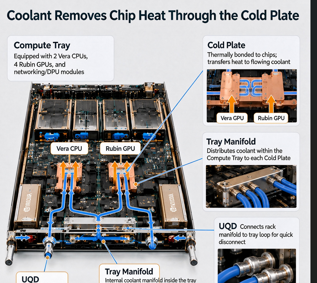
The tray manifold handles secondary flow distribution inside one tray, a newly developed structure built for Rubin on the 3rd-generation MGX platform. A standard compute tray holds 2 Vera CPUs + 4 Rubin GPUs, alongside ConnectX-9, BlueField-4 and other network chips. Rubin compute trays adopt a hose-free layout. Modular manifolds and hard interfaces replace scattered flexible hoses inside traditional trays, reducing hose aging and joint leakage points. No fans are installed inside trays; all thermal loads are borne by the liquid cooling loop.
6. Coolant Path 5: Cold Plate
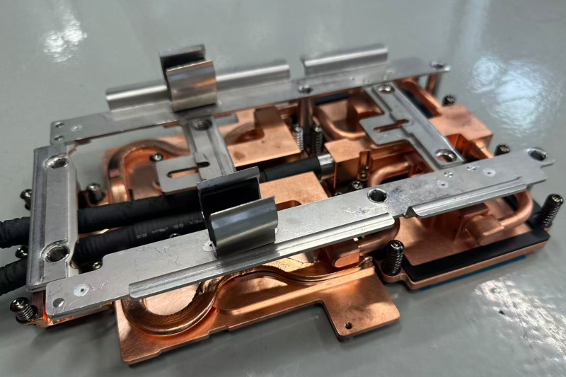
After distribution from the tray manifold, coolant flows into cold plates bonded directly to chips. A cold plate is a metallic heat exchanger with internal flow channels. Chip heat transfers through the package and thermal interface material (TIM) to the cold plate wall, then gets carried away by flowing coolant. Rubin liquid cooling is not limited to GPUs. CPUs, NVLink switch chips, network adapters and all network components are connected to the closed liquid cooling loop. The 9 NVLink switch trays share identical cold plate design as compute trays.
Two core transfer chains Coolant flow path: Tray Manifold → Cold Plate Heat transfer path: Vera CPU / Rubin GPU / Network Chips → Cold Plate → Coolant
Cold Plate Process: FSW / Vacuum Brazing, Base Material, Channel Type, Thermal Resistance
- Friction Stir Welding (FSW) Cold Plate
- Base material: 6063 / 1060 aluminum, pure copper; solid-state welding without filler metal
- Channel type: milled enclosed channel, channel with skived fin insert
- Thermal resistance: 0.015~0.025 °C/W. Weld thermal conductivity matches base material, with no void risk from brazing filler. Suitable for long-term continuous operation under high power density, delivering better anti-aging and anti-leaching performance.
- Vacuum Brazed Cold Plate
- Base material: copper, aluminum, copper-aluminum composite; sealed with brazing filler
- Channel type: multi-layer stacked microchannel, cross fin turbulence structure
- Thermal resistance: 0.012~0.018 °C/W, lower thermal resistance floor. Ideal for strict hot spot suppression. Limitation: interfacial thermal resistance at brazing layer, risk of filler corrosion and ion leaching under long-term thermal cycling.
7. Return Flow: Heat Recirculation & Closed Loop
After absorbing heat, coolant flows back in the return direction:
- Heated coolant from individual cold plates converges into the tray manifold
- Coolant flows out of the compute tray via UQD
- Return fluid from all trays collects at the rack manifold
- Fluid returns to CDU to complete the server-side closed loop
✅ Full server-side liquid cooling loop: CDU → Rack Manifold → UQD → Tray Manifold → Cold Plate → Tray Manifold → UQD → Rack Manifold → CDU
✅ Full heat transfer chain: Chip → Cold Plate → Server-side Coolant → CDU Heat Exchanger → Facility Water → Dry Cooler / Chiller → Ambient Environment
8. O&M Risk List: Leak Detection, Fluid Corrosion, Ionic Contamination, Maintenance Interval
Failure risks of full liquid cooling systems concentrate on fluid loops, with more complex operation boundaries than air-cooled servers.
- Leak Detection
- Passive protection: UQD spill tray, tray bottom leak sensor, conductive leak rope
- Active monitoring: branch flow sensor, differential pressure alarm; sudden flow drop or pressure deviation indicates potential connector leakage
- Risk factors: O-ring aging after thermal cycling, connector misalignment, micro-leakage from assembly stress
- Fluid Corrosion
- Root causes: pH drift, dissolved oxygen, inhibitor depletion; copper cold plates release copper ions, aluminum substrates are prone to pitting corrosion
- Control method: closed deionized loop, regular inhibitor top-up, pH maintained at 7.5–9.0
- Ionic Contamination
- Sources: brazing residue, filler leaching, pipeline debris, ions from makeup water
- Hazard: ions deposit on substrate and PCB, trigger leakage current and electrochemical migration under high voltage, leading to GPU failure
- Monitoring metric: coolant conductivity; target conductivity below 1 μS/cm for computing liquid cooling systems
- Reference Maintenance Schedule
- Monthly: Visual inspection of UQD connectors, leak sensor status check
- Quarterly: CDU filter differential pressure check, pump vibration inspection
- Semi-annually: Coolant sampling test (conductivity, pH, ion concentration, microbiology), O-ring aging assessment
- Annually: Full loop flushing, seal replacement; shorten interval for high-load racks
9. Technical Trend Summary
Vera Rubin NVL72 realizes 45°C warm-water and full-rack liquid cooling, extending heat dissipation coverage to GPUs, CPUs, network chips and high-current busbars, deeply integrated with data center facility infrastructure. NVIDIA continues to raise rack computing density, and the next-generation Kyber rack will still adopt liquid cooling as the core thermal solution for high-density rack computing. From the disassembly perspective, every component including cold plate, UQD, manifold and CDU can be further split into material selection, welding, sealing and pressure testing details, which are core development directions for thermal management ODM heat sinks and liquid cooling plates supplier.
What can Kenfa Tech can help your thermal projects?
Kenfa tech delivers cold plate design, FSW / vacuum brazed cold plate prototyping, UQD selection and thermal simulation validation for GB200 / GB300 / Vera Rubin NVL72. Contact us for DFM and thermal resistance simulation reports if you need custom cross fin microchannel cold plates or 4Cr pressure-bearing structural modules. so you can email to us king@kenfatech.com or linkedin us