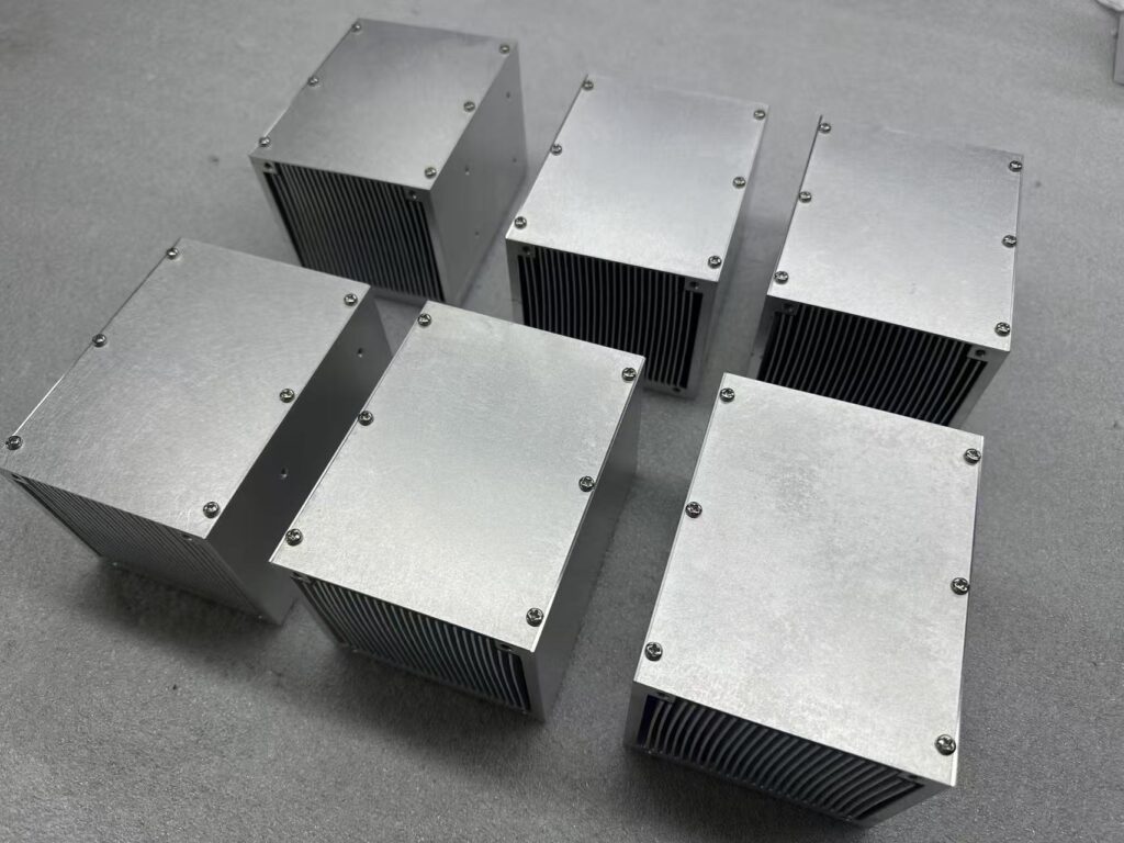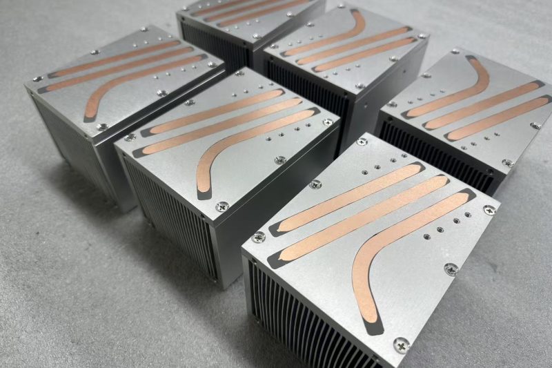
150W Laser Module Heat Pipe Heat Sink Optimization Case | Gravity-Assisted Layout + Skived Fin for Compact High-Performance Cooling.
1,Project Overview
We received a custom thermal demand from a customer for a laser module. The target heat load is 150W, with a strict envelope dimension of 120×120×100 mm. A 120×120×38 mm fan is matched for forced air cooling.
The customer’s preliminary concept adopted horizontally parallel heat pipes. After thermal simulation, we identified critical performance limits of this layout and carried out multi-round structural optimization. The final prototype passed customer testing with highly satisfactory thermal results.
2,Pain Points of the Original Design
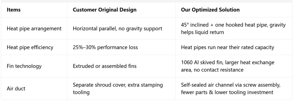
In the customer’s initial layout, heat pipes were arranged horizontally in parallel. Our thermal analysis confirmed that without gravity assistance, condensate inside heat pipes can only flow back by capillary force. This causes the effective heat transfer efficiency of heat pipes to drop by 25%–30%.
For continuous 150W laser operation, this may lead to dry-out at the evaporator section, higher thermal resistance, excessive laser temperature rise and poor long-term working stability.We tested fin thickness from 1.0 mm to 1.2 mm. Through simulation in Ansys Icepak, our thermal management software, we found the optimal configuration: 1.0 mm fin thickness with 2.5 mm fin pitch. In addition, we identified 10 mm for the base plate thickness and 110 mm for fin height as the best-performing dimensions.
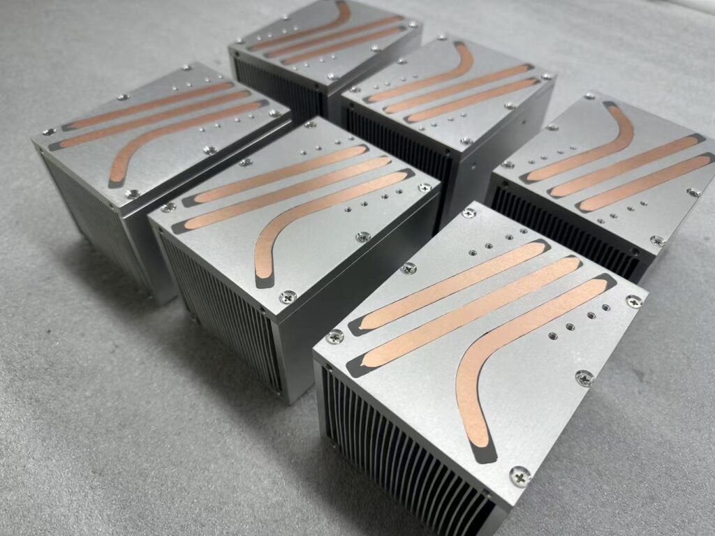
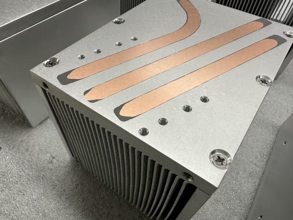
We use heat pipes with sintered composite capillary wick structure. Each 9.52 mm diameter heat pipe is rated to transfer 80 W. With three heat pipes installed, the total theoretical heat capacity is 240 W. This overcapacity layout is reserved for the customer’s future power upgrade and product evolution, offering great flexibility for their subsequent product iteration.We use heat pipes with a wall thickness of 1.0 mm. The heat pipes are embedded into the heat sink base plate, and epoxy resin fills the gaps within the grooves. This lowers the interfacial thermal resistance between the heat pipes and the heat sink substrate.
3. Three Core Optimization Measures
Heat pipe layout upgrade: gravity-enhanced liquid return
We reoriented the heat pipes at a 45° inclined angle. One heat pipe was further designed with a hooked reverse bend. This design combines capillary force and gravity to speed up condensate return to the evaporator end, maximizing heat pipe performance and avoiding the efficiency loss of horizontal installation.
2. Material & process selection: 1060 aluminum + skived fin
The heat sink base and fins use 1060 aluminum with the skived fin process. Fins are formed as one solid piece with the base, eliminating interfacial thermal resistance. Within the limited 120×120×100 mm space, this structure delivers the largest possible heat exchange area for convection cooling.
3. Innovative air duct design to cut cost
We removed the separate air shroud cover used in traditional designs. With screw locking assembly, the heat sink and fan form a closed air channel by themselves. This eliminates one extra component and saves tooling cost for stamping and bending of the shroud. Thermal performance stays unchanged while the total BOM cost is reduced.
4. Comparison Between Initial and Optimized Design
5. Applicable Scenarios
This design logic works well for air-cooled thermal solutions with 100–200W heat sources, including high-power laser modules, industrial light sources, LiDAR and compact industrial control hardware. It fits custom cooling projects with tight space constraints and a priority to balance thermal performance and tooling budget.
6. FAQ
Q: Why choose 45° tilt instead of full vertical 90°?
A: Vertical mounting gives the strongest gravity return, but it is often restricted by package size and component placement. The 45° angle is the balance point for this specific envelope, which keeps installation feasible while preserving most gravity benefits. The hooked heat pipe adds extra backup for stable liquid circulation under extreme working conditions.
Q: What advantages does skived fin have over extruded aluminum fins?
A: Skived fin can produce thinner, denser fins within the same volume to get more heat transfer area. Since fins and base are monolithic, there is no interfacial thermal resistance. It suits low-to-medium volume custom projects without expensive extrusion tooling.
If you face thermal challenges for laser modules, optical components or industrial hardware with fixed space limits and tight requirements for performance & cost, send your drawings and specs to us for thermal simulation review. Kenfa Tech provides custom cooling solutions including heat pipe heat sinks, skived fin assemblies and cold plates.You may also visit our Kenfa linkedIn page to learn more about our latest products.