
Abstract
From 400G to 800G and 1.6T, the core bottleneck of high-speed optical modules shifts from transmission capability to temperature control. Wavelength drift of laser diodes, hotspots on DSP chips, system power budgets and data center infrastructure constraints form intertwined challenges. TEC, liquid cooling and forced thermal air forcing serve distinct roles within a layered thermal architecture. This article avoids simplistic one-to-one technical comparison. It analyses scenario boundaries, cost structures and long-term reliability trade-offs. In AI compute clusters, optical modules evolve into compact high-heat components. Typical 800G modules consume 25–30 W, while high-power 1.6T variants exceed 45 W within unchanged form factors. Local heat flux surpasses 100 W/cm², approaching the hard limit of conventional air cooling.
Temperature variation triggers wavelength drift of DFB lasers at approximately 0.1 nm/°C. EML modulators exhibit even stricter thermal sensitivity. For DWDM and LAN-WDM systems with narrow channel spacing, temperature fluctuation causes wavelength offset, crosstalk, increased BER and accelerated laser degradation, which reduces MTBF. The industry builds a three-layer thermal framework: chip-level precision temperature regulation, module-level heat spreading and rack/switch-level heat evacuation. TEC, liquid cooling plate and thermal air forcing are complementary rather than mutually exclusive solutions in this hierarchy.
1. Introduction
Bandwidth demand driven by large-scale AI compute clusters pushes optical interconnects toward 800G and 1.6T. Public discussion often focuses on modulation formats, DSP performance and fibre loss. Thermal behaviour remains an underrated limiting factor.
Optical modules are not uniform heat sources. Heat concentrates on DFB lasers, EML modulators, SOAs and DSP dies. Thermal requirements split into two separate targets:
- Maintain precise junction temperature for wavelength-sensitive photonic chips;
- Extract bulk heat from the module shell to satisfy total power budgets.
Many engineers mistakenly treat TEC, liquid cooling and forced thermal air forcing as competing alternatives. In practice, each scheme occupies a defined operating envelope with inherent trade-offs. This paper clarifies where each solution fits, and how hybrid architectures dominate high-end deployments.
2. TEC: Precision Chip-Level Temperature Regulation with a Clear Power Ceiling
TEC operates on the Peltier effect. Controlled current transfers heat between its cold and hot sides. The cold side attaches directly to temperature-sensitive photonic components, locking temperature tolerance down to ±0.1 °C or better. It is an indispensable foundation for DWDM and coherent long-reach modules.
Its primary function is not bulk heat removal. TEC isolates photonic chips from ambient disturbance and stabilises optical operating points. Short-reach SR/DR modules commonly omit TEC because their wavelength tolerance is wider. Passive conduction through the housing is sufficient.
2.1 Advantages and applicable boundaries
- Miniature footprint. Micro-TEC can integrate directly on AlN ceramic substrates and co-package with photonic chips;
- Fast closed-loop response. It stabilises laser wavelength under wide ambient temperature swings;
- Mature supply chain and standardised packaging. It fits existing QSFP-DD and OSFP form factors without switch or rack reconstruction.
2.2 Inherent limitations
TEC consumes additional power for heat pumping. Its COP is intrinsically low. Larger temperature lift increases auxiliary power draw, which counts against the module total power budget. At 1.6T and above, cumulative TEC power overhead forces system derating.
TEC only transports heat. All heat extracted on the cold side dissipates through its hot junction into the module housing. The downstream cooling system must remove this accumulated heat. A blocked thermal path on the hot side leads to thermal runaway and sudden loss of cooling capacity.
Boundary summary: TEC is mandatory for photonic devices requiring stable wavelength and optical power. It supports local precision control but cannot act as the primary bulk cooling method for high-power modules. The TEC-less trend in LPO short-reach silicon photonics is a deliberate architecture trade-off to save power.
3. Liquid Cooling: Primary Bulk Heat Evacuation for High-Power Generations, Restricted by Infrastructure and Maintenance
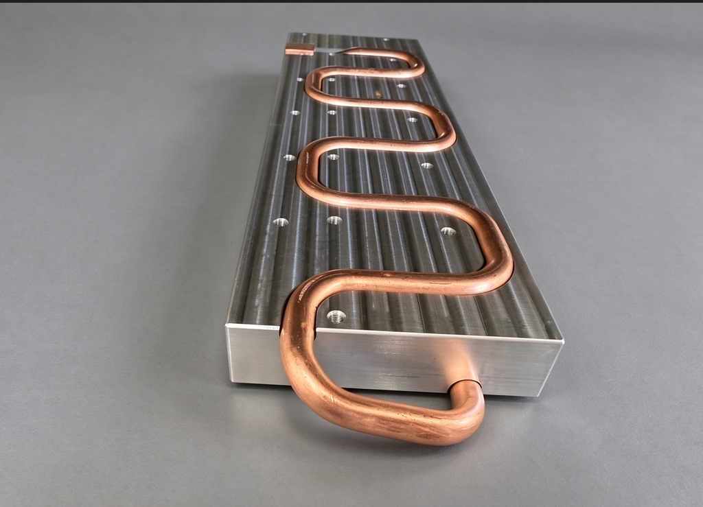
When module power exceeds 30 W and switches run fully populated, conventional air cages suffer high contact thermal resistance and airflow bottlenecks. Three liquid cooling routes have emerged for optical modules, with sharply different use cases.
- Compliant cold plate (floating cold plate): Cold plates embed inside switch cages. The inserted module shell contacts the cold plate for heat exchange. This is the mainstream transition solution for 800G to 1.6T. It maintains compatibility with existing OSFP packaging and requires no internal fluid channel inside the module. Retrofit from air-cooled data centres is feasible. Consistency depends heavily on TIM performance and contact pressure. Insertion tolerance creates variability risk.
- Module-integrated microchannel LCO: Microchannels embed inside the module body with blind-mate quick connectors. Coolant reaches heat sources directly. This design supports heat removal up to 80 W and targets next-generation high-power pluggable form factors such as XPO. Drawbacks include structural redesign, sealing validation, leakage reliability testing and substantial cost growth.
- Immersion cooling: Entire racks submerge in dielectric coolant. Uniform surface heat transfer supports rack power above 60 kW for ultra-dense compute clusters. Material compatibility constraints apply to connectors, optical adhesives and seals. Operation complexity limits large-scale rollout. It rarely retrofits existing switch hardware.
Liquid cooling delivers low thermal resistance and suppresses shell temperature. It reduces the required temperature lift for paired TEC devices. The prevailing high-end 1.6T architecture combines liquid cooling for base heat load and miniature TEC for fine wavelength trimming. This combination cuts TEC power consumption significantly.
Liquid cooling is a system-level upgrade rather than a component modification. Capital expenditure covers cold plates, piping, pumps, CDU, leak detection and site piping renovation. Liquid-cooled cages carry higher unit cost than air versions. Long-term burdens include leakage risk and overhauled spare-part workflows.
Boundary summary: Liquid cooling fits ultra-dense AI clusters and high-power 1.6T / 3.2T deployments with high rack power density. Standard IDC and carrier edge sites with low-power modules gain little economic benefit from forced liquid cooling deployment.
4. Forced Thermal Air Forcing: Low-Cost Control for Testing and Mild Thermal Scenarios, Constrained in Mass Production Deployment
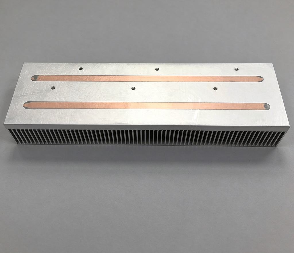
Heat sink is Forced thermal air forcing applies closed-loop temperature-controlled airflow around the module. It stabilises housing temperature by regulating surrounding air. It differs fundamentally from conventional switch air cooling: ordinary air cooling aims to maximise heat removal, while thermal air forcing actively holds ambient temperature within a target window.
Its most mature application lies in production testing, reliability screening and temperature cycling. Directed airflow enables fast temperature ramping without solid contact. Optical probes and fibre access remain unobstructed, making it standard equipment for wavelength sweep, BER testing and high-temperature ageing.
Direct deployment inside data centre switches carries narrow limits. Its strengths include zero TEC power overhead, no fluid infrastructure and low mechanical complexity. It suits low-power modules with relaxed thermal tolerance and controllable ducting.
Critical drawbacks restrict broader adoption:
- Temperature uniformity rarely reaches ±1 °C, insufficient for DWDM and coherent laser stability;
- Air-side heat transfer coefficient caps cooling capacity. High heat flux demands extreme airflow, fan power and acoustic noise;
- Cross-port airflow interference creates uneven conditions across switch slots, hurting batch consistency.
Boundary summary: Thermal air forcing belongs to ambient-side conditioning instead of die-level precision control. It is optimal for test and ageing stations. It cannot serve as the primary thermal solution for high-power, DWDM or coherent modules in dense compute racks.
5. Industrial Trade-offs: Layered Matching Rather Than Single-Scheme Selection
Four core criteria guide thermal architecture selection: module power rating, photonic device type (DWDM / coherent or short-reach), rack power density and existing data centre infrastructure.
- Carrier long-haul DWDM and ZR coherent modules: TEC is mandatory. Air cooling works as baseline heat evacuation. Liquid cooling upgrades apply in high-density racks to reduce TEC load. Thermal air forcing is limited to test stages.
- Conventional IDC low-power 800G DR/SR and LPO modules: TEC-free design paired with passive shell cooling delivers optimal cost-performance. Liquid cooling brings no advantage.
- High-power 1.6T+ OSFP modules in AI clusters: Shell-side cold plate liquid cooling handles bulk heat. Micro-TEC retains laser wavelength lock. This hybrid stack represents today’s leading configuration.
- Production test and burn-in: Thermal air forcing provides flexible, high-throughput screening alongside TEC and liquid cooling fixtures.
The rise of LPO highlights a major industry trade-off. Eliminating TEC reduces auxiliary power consumption, yet optical performance becomes more temperature-sensitive. LPO designs impose stricter requirements on housing thermal spreading and cooling uniformity. This represents a deliberate shift from active chip refrigeration toward passive system-side thermal management.
CPO reshapes the established boundary further. Photonic engines co-locate tightly with switch ASICs, creating strong thermal coupling. Discrete TEC and pluggable liquid cages are no longer suitable. Thermal design shifts from standalone module engineering toward co-optimisation across die, package, substrate and cold plate. Thermal management moves from a peripheral requirement to an upfront architectural constraint.
| Parameter | TEC (Thermoelectric Cooler) | Liquid Cooling (Compliant Cold Plate / Microchannel LCO) | Forced Thermal Air Forcing |
|---|---|---|---|
| Control precision | ±0.1 °C or better at chip level; locks laser wavelength directly | Housing temperature regulated to roughly ±2–3 °C; die-level precision depends on a paired micro-TEC | ±1 °C is hard to hold in practice; typically ±1–3 °C across ports |
| Heat removal capacity | No bulk heat removal. Transports heat only; final rejection depends entirely on the downstream hot-side path | Compliant cold plate ≈ 40–50 W/module; integrated microchannel LCO 80 W+; immersion substantially higher | Low. Practical ceiling around 15 W/module; airflow bottleneck becomes severe as power rises |
| Added power consumption | High. Low COP; overhead grows steeply with temperature lift and counts directly against the module power budget | Negligible at module level; pump, CDU and facility power sit at system level | Fan power only; no active refrigeration load |
| Infrastructure requirement | Low. Fits existing QSFP-DD / OSFP cages; no switch or rack modification | High. Cold plates, manifolds, pumps, CDU, leak detection and facility piping retrofit; brownfield conversion is costly | Low. Fixture, ducting and blower only; no fluid loop |
| MTBF risk points | TEC element aging under thermal cycling; hot-side blockage triggers thermal runaway and abrupt loss of cooling capacity | Seal and blind-mate connector leakage, coolant contamination, corrosion, insertion-tolerance wear on the TIM interface | Fan wear-out; cross-port airflow interference causes uneven batch temperature, accelerating device aging |
| Cost range | Moderate device cost; mature, standardised supply chain; scalable in volume | High CAPEX per port. Cold plate, quick-disconnect, CDU and leak monitoring dominate the cost stack | Low. Simplest bill of materials; ideal for high-throughput production lines |
6. Conclusion
Simplified narratives claiming liquid cooling replaces TEC or TEC faces obsolescence miss fundamental engineering reality. Liquid cooling removes bulk heat. TEC stabilises photonic operating points. Thermal air forcing delivers controlled ambient conditions for validation. Their core objectives do not compete.
Future thermal ecosystems for high-speed optical modules will rely on layered combinations. Micro-TEC secures wavelength precision at the chip level. Air or liquid cooling serves as the primary heat evacuation layer according to rack density. Thermal air forcing remains the workhorse for reliability validation.
For equipment vendors, cloud operators and module suppliers, technology selection should follow scenario mapping instead of chasing cutting-edge labels. Decision makers need to assess wavelength sensitivity, sustained power envelope and site infrastructure readiness. Bandwidth competition in AI compute clusters ultimately comes down to thermal budgets per port. Temperature control capability forms the invisible ceiling of next-generation optical interconnects.